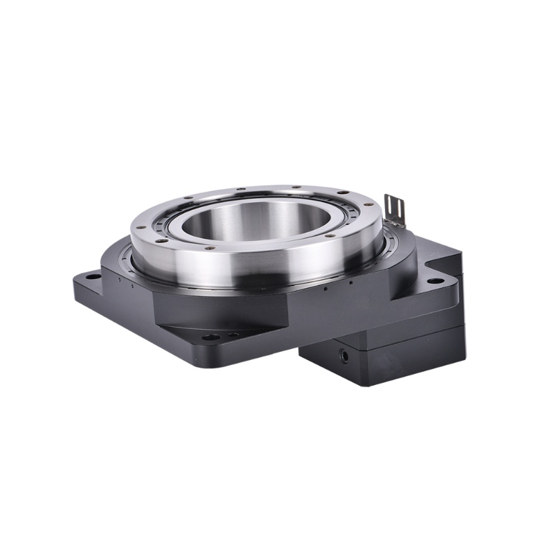


Product Description
Electric Table Cylinder Linear Slide is a mechanical end effector for achieving linear reciprocating motion, which cleverly combines electric actuators (electric cylinders) and linear slide guides. It uses motor drive (such as servo motors, stepper motors) to replace traditional pneumatic/hydraulic cylinders to achieve high-precision, programmable linear reciprocating motion, while having the guidance and load support functions of the slide. It is widely used in automation equipment, precision instruments, industrial machinery and other fields. Its core function is to provide high-precision and stable linear displacement.
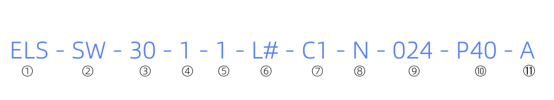
①ELS ②SW ③ Stroke ④Lead
ELS: Product Series SW: small width, none: standard width 30:30MM 1: 1MM
50:50MM 2: 2MM
4: 4MM
6: 6MM
⑤ Wire outlet position ⑥ Cable fixed end length ⑦Communication mode ⑧Brake
0: Side outlet L#: default 200mm C0: 485 N: Without brake
1: Tail outlet L5000: 5000mm C1: 485+1/O (NN) O: With brake
C2: 485+1/0 (PP)
C3: 485+1/O (NP)
C4: 485+1/0 (PN)
⑨Power supply voltage ⑩IP level ⑪Model version (customer configuration
024:24V P40: IP40 A: Default
B: First upgrade
C: Second upgrade
.....
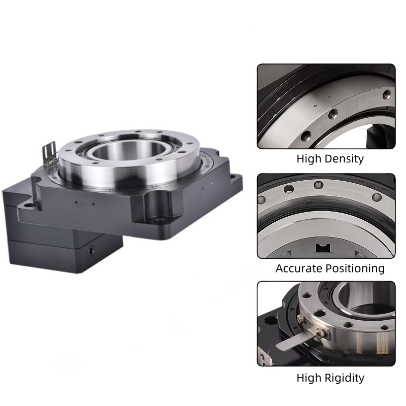
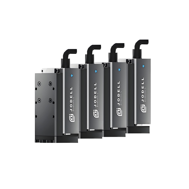
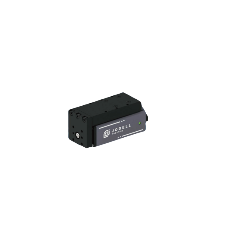
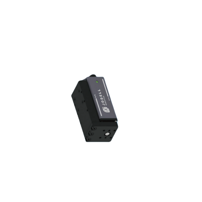
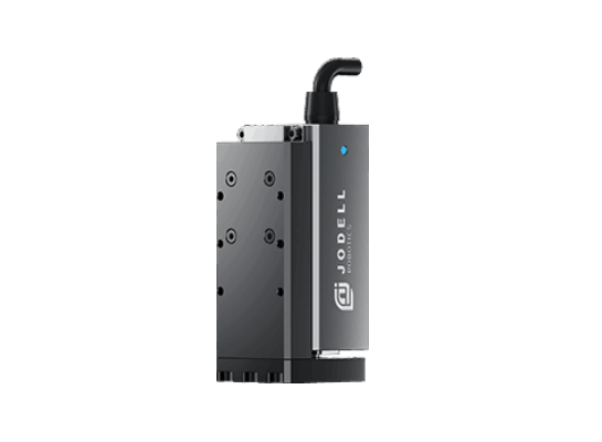
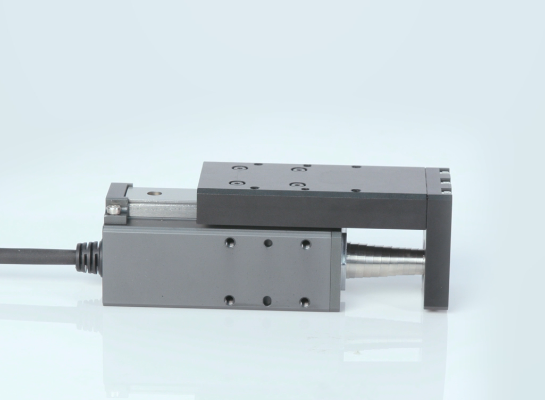
Product Display
High precision (±0.004mm ~ ±0.02mm), far exceeding ordinary cylinders
Programmable control (speed, position, acceleration adjustable)
Maintenance-free (no air source required, reducing the risk of air leakage)
Low noise (quieter than pneumatic systems)
Long life (electric drive, no cylinder seal wear problem)
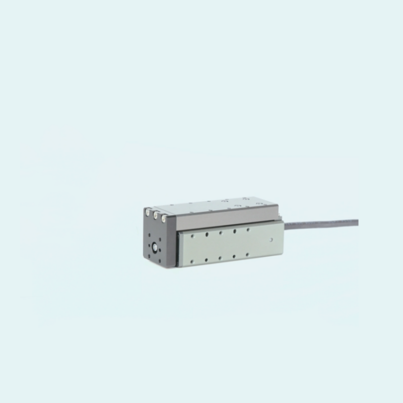
Linear guide rails High-precision guide rails (such as HIWIN guide rails)
Sliders Load-bearing components that move along the guide rails
Ball screws Convert motor rotation into linear motion
Servo motors Provide power (such as 400W servos)
Couplings Connect motors and screws
End caps/supports Fix screws and guide rails at both ends
Limit switches Control travel range
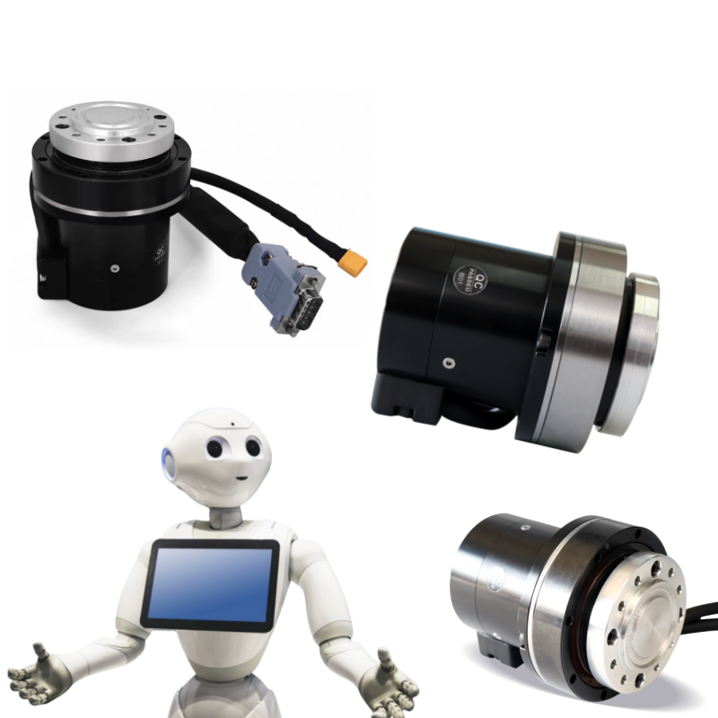
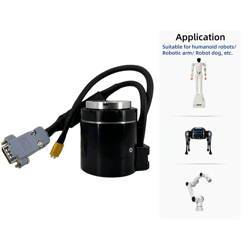
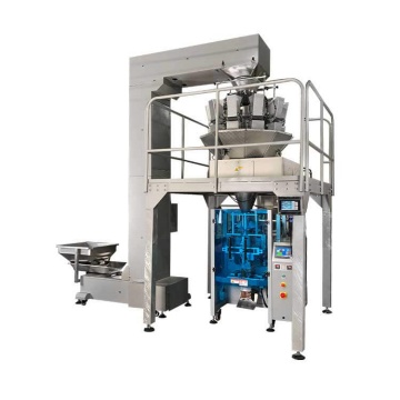
Application
A linear actuator is a device that converts electrical energy, hydraulic energy or pneumatic energy into linear motion. It is widely used in the fields of industry, medical treatment, home, transportation, etc. In industrial automation, it is used for machine tool positioning, assembly line push and packaging machinery control; in medical equipment, it drives surgical robots and adjusts electric beds; in smart homes, it realizes automatic control of lifting tables and electric curtains; in transportation, it is used for car tailgates, seat adjustment, etc. In addition, it is also used in agricultural machinery, solar tracking systems and valve control. Its core advantages lie in precise positioning, efficient driving and stable performance. It can adapt to different load and environmental requirements and promote the development of automation technology.

Product parameters
Parameters | ELS-HP30 | ELS-HP50 | ||||||
Total stroke | 30mm | 50mm | ||||||
Screw lead | 1mm | 2mm | 4mm | 6mm | 1mm | 2mm | 4mm | 6mm |
Rated thrust | 200N | 100N | 50N | 30N | 200N | 100N | 50N | 30N |
Minimum thrust | 60N | 30N | 15N | 9N | 60N | 30N | 15N | 9N |
Maximum speed | 50mm/s | 100mm/s | 200mm/s | 300mm/s | 50mm/s | 100mm/s | 200mm/s | 300mm/s |
Maximum acceleration | 0.2 | 0.3 | 0.3 | 0.3 | 0.2 | 0.3 | 0.3 | 0.3 |
Maximum load capacity - horizontal | 8kg | 6kg | 3kg | 2kg | 8kg | 6kg | 3kg | 2kg |
Maximum load capacity - vertical | 2kg | 1.5kg | 0.75kg | 0.5kg | 2kg | 1.5kg | 0.75kg | 0.5kg |
Repeat position accuracy | ±0.004mm | |||||||
Absolute position accuracy | ±0.01mm | |||||||
Body width | 45mm | |||||||
Function description | Position mode/Push mode | |||||||
Driver | Built in | |||||||
Protection level | IP40 | |||||||
Recommended operating environment | 0~40°C,<85% RH | |||||||
Rated voltage | DC 24V±10% | |||||||
Rated current | 1.5A | |||||||
Peak current | 3A | |||||||
Static allowable load moment Mx | 32 N·m | |||||||
Static allowable load moment My | 20 N·m | |||||||
Static allowable load moment Mz | 23 N·m | |||||||
Dynamic allowable load moment Mx | 12.5 N·m | |||||||
Dynamic allowable load moment My | 10N·m | |||||||
Dynamic allowable load moment Mz | 10N·m | |||||||
ELS-HP30-X-XP-L200-C7-X-A-P40-S00
ELS-HP50-X-XP-L200-C7-X-A-P40-S00
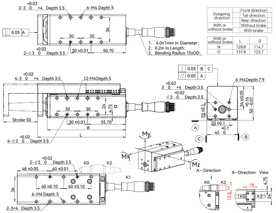
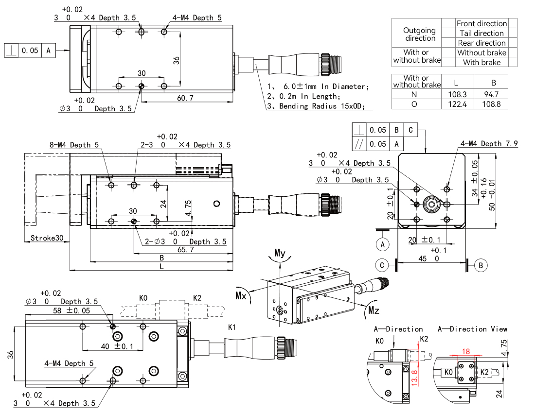
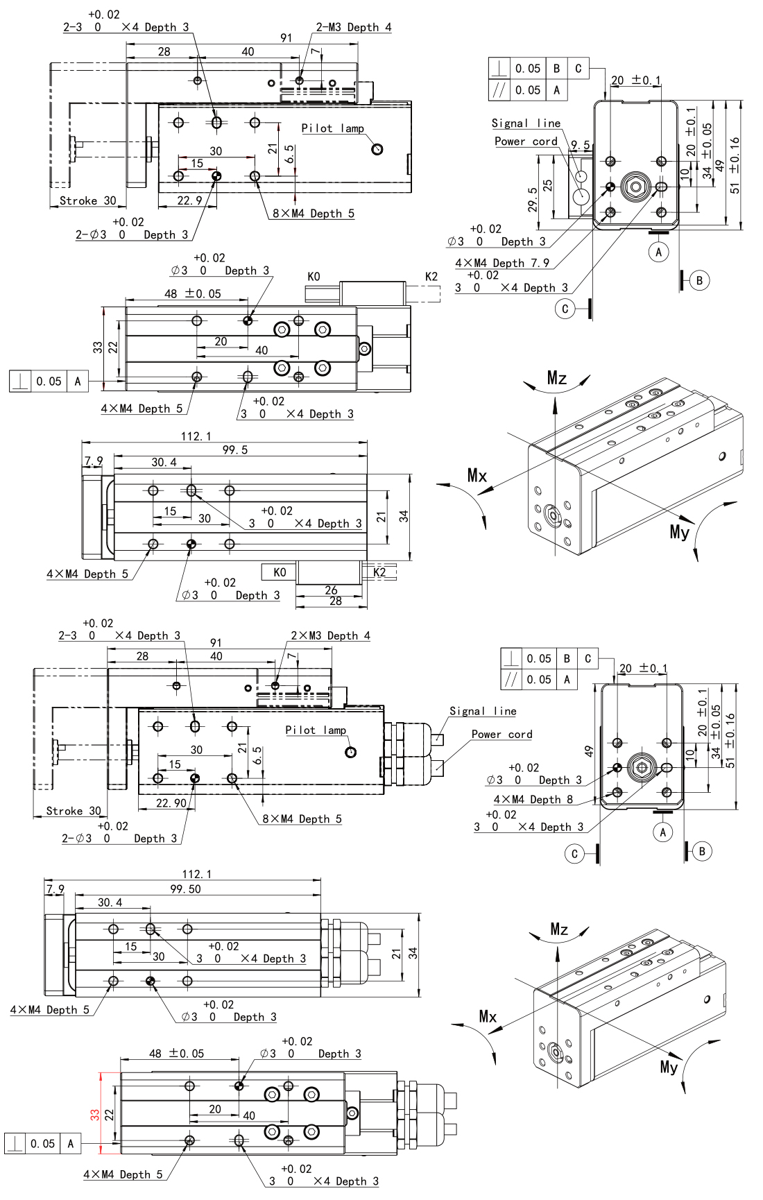
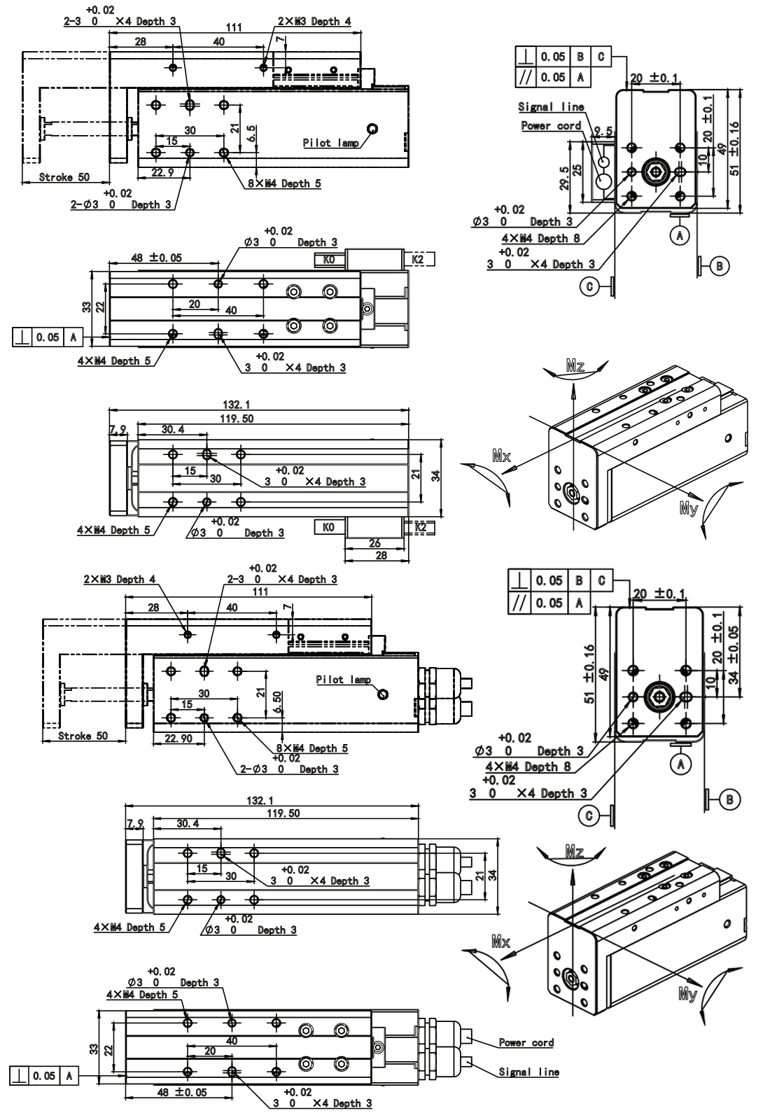
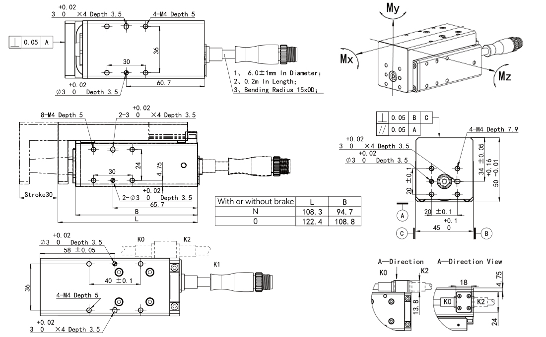
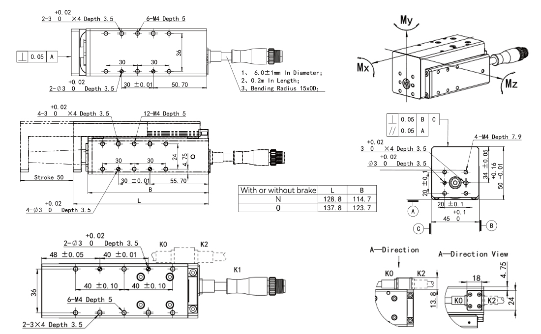
Model | ELS-SW | ELS--30 | ELS--50 | |||||||||
Total stroke | 30,50mm | 30mm | 50mm | |||||||||
Screw lead mm | 1mm | 2mm | 4mm | 6mm | 1mm | 2mm | 4mm | 6mm | 1mm | 2mm | 4mm | 6mm |
Rated thrust N | 200N | 100N | 50N | 30N | 200N | 100N | 50N | 30N | 200N | 100N | 50N | 30N |
Minimum thrust N | 60N | 30N | 15N | 9N | 60N | 30N | 15N | 9N | 60N | 30N | 15N | 9N |
Maximum speed mm/s | 50mm/s | 100mm/s | 200mm/s | 300mm/s | 50mm/s | 100mm/s | 200mm/s | 300mm/s | 50mm/s | 100mm/s | 200mm/s | 300mm/s |
Maximum acceleration G | 0.2 | 0.3 | 0.3 | 0.3 | 0.2 | 0.3 | 0.3 | 0.3 | 0.2 | 0.3 | 0.3 | 0.3 |
Maximum loadable weight - horizontal kg | 8kg | 6kg | 3kg | 2kg | 8kg | 6kg | 3kg | 2kg | 8kg | 6kg | 3kg | 2kg |
Maximum loadable weight - vertical kg | 2kg | 1.5kg | 0.75kg | 0.5kg | 2kg | 1.5kg | 0.75kg | 0.5kg | 2kg | 1.5kg | 0.75kg | 0.5kg |
Rated voltage V | 24 V DC 士10% | 24 V DC 士10% | 24 V DC 士10% | |||||||||
Rated current A | 1.5A | 1.5A | 1.5A | |||||||||
Peak current A | 3A | 3A | 3A | |||||||||
Rated power W | 20w | 20w | 20w | |||||||||
Motor type | DC Servo Motor | DC Servo Motor | DC Servo Motor | |||||||||
Static allowable load torque Ma | 14N.m | 14N.m | 14N.m | |||||||||
Static allowable load torque Mb | 14N.m | 14N.m | 14N.m | |||||||||
Static allowable load torque Mc | 6N·m | 24N·m | 24N·m | |||||||||
Position repeatability mm | ±0.02mm | ±0.02mm | ±0.02mm | |||||||||
Body width mm | 35mm | 45mm | 45mm | |||||||||
Function description | Position mode / Push mode | |||||||||||
Communication protocol | Built-in: Modbus RTU (RS485); Digital I/O, IO-link optional | |||||||||||
Protection level | IP40 | |||||||||||
Recommended use environment | 0~40°C,<85% RH | |||||||||||
Complies with international standards | CE,FCC,RoHS | |||||||||||
Travel life | 50 million round trips / 5000Km | |||||||||||
Installation method | Horizontal installation, vertical installation, side installation, ceiling installation | |||||||||||
Interface cable outlet method | Rear outlet / Side outlet | |||||||||||
ELS-SW-30-2-1S-L200-0-O-A-P40-S00
ELS-SW-50-2-1S-L200-0-O-A-P40-S00
ELS-30-2-1P-L200-C7-O-A-P40-S00
 ELS-50-2-1P-L200-C7-O-A-P40-S00
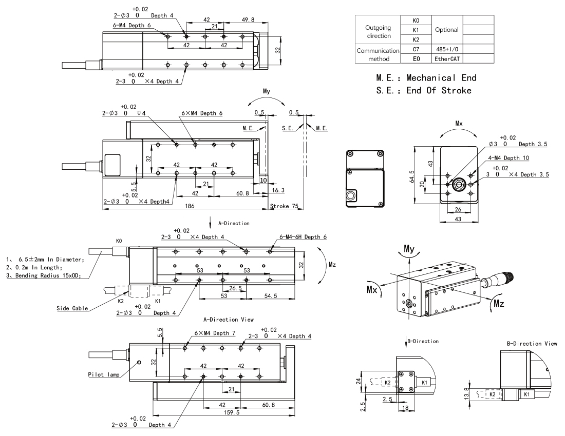
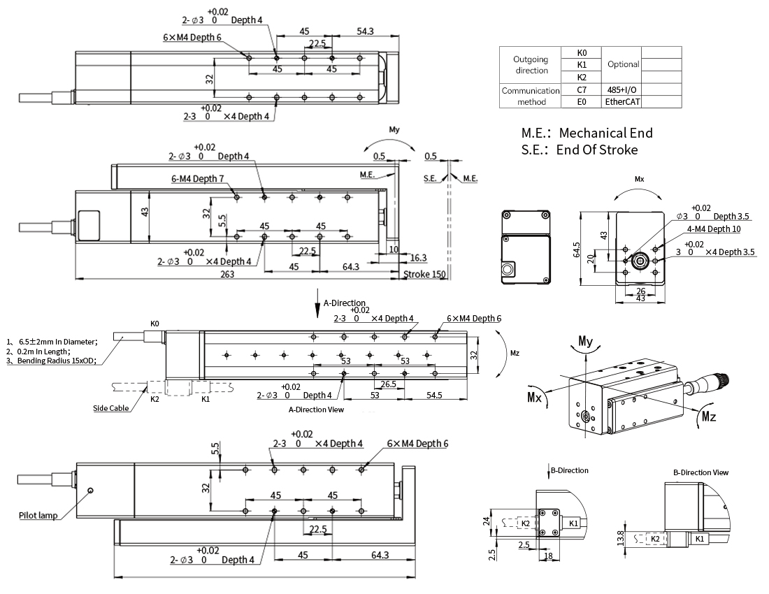
Model | ELS--75 | ELS-150 |
Total stroke | 75mm | 150mm |
Screw lead mm | 5mm | 10mm |
Rated thrust N | 170N | 90N |
Minimum thrust N | 51N | 20N |
Maximum speed mm/s | 250mm/s | 500mm/s |
Maximum acceleration G | 2000mm/s^2 | 3000mm/s^2 |
Maximum load - horizontal | 15kg | 10kg |
Maximum load - vertical | 6kg | 3kg |
Position repeatability | ±0.02mm | ±0.02mm |
Brake | Built-in brake | |
Communication protocol | Modbus RTU(RS485)+Digital I/O | |
Driver | built-in | |
Body width | 43mm | 43mm |
Body weight | 1.3kg | 1.8kg |
Protection level | IP40 | IP40 |
Rated voltage | DC 24V ±10% | DC 24V ±10% |
Rated current | 3A | 2.5A |
Peak current | 7A | 7A |
Recommended operating environment | 0~40°C, 85% RH or less | |
Cable length | The main cable is 0.2m long, and the included cable is 5m long | |
Static allowable load moment Mx | 38.2 N·m | 38.2 N·m |
Static allowable load moment My | 36.2N·m | 36.2N·m |
Static allowable load moment Mz | 36.2 N·m | 36.2 N·m |
Dynamic allowable load moment Mx | 15.2 N·m | 15.2 N·m |
Dynamic allowable load moment My | 14.5 N·m | 14.5 N·m |
Dynamic allowable load moment Mz | 14.5 N·m | 14.5 N·m |
ELS-75-5-1P-L200-C7-O-A-P40-S00
ELS-150-10-1P-L200-C7-O-A-P40-S00
Service
1. Fast delivery of standard products: Conventional models are in stock, tested before shipment, and shipped within 5 working days.
2. Logistics progress tracking: After delivery, the waybill number and real-time logistics information are provided,
and flexible transportation methods such as air/land transportation are supported.
3. Installation, commissioning and calibration: Provide professional installation guidance to ensure
that the equipment reaches the best operating state and meets the requirements of repeated positioning within ±5 arc seconds.
4. Maintenance and fault diagnosis: Provide regular maintenance recommendations,
wear parts replacement and remote troubleshooting services to extend the life of the equipment and ensure long-term stable operation.
5. Automation system integration: Support collaborative integration with robots, PLCs, and motion controllers,
provide software and hardware interface development and multi-axis linkage control solutions, and realize intelligent production line upgrades.