
Product Description
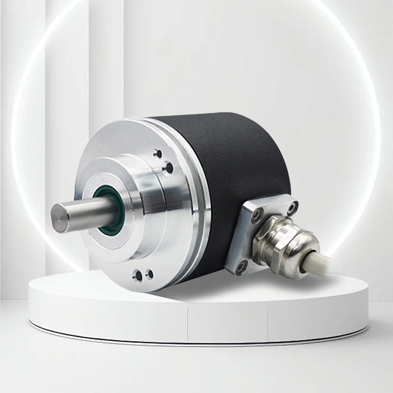
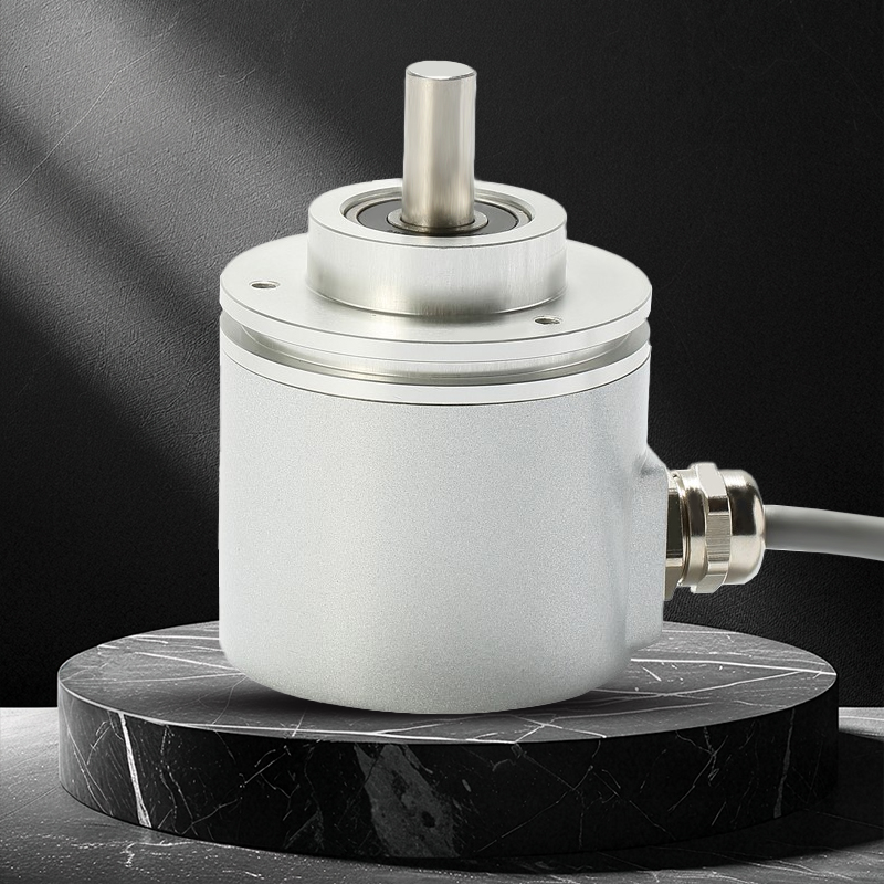
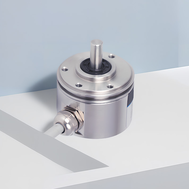
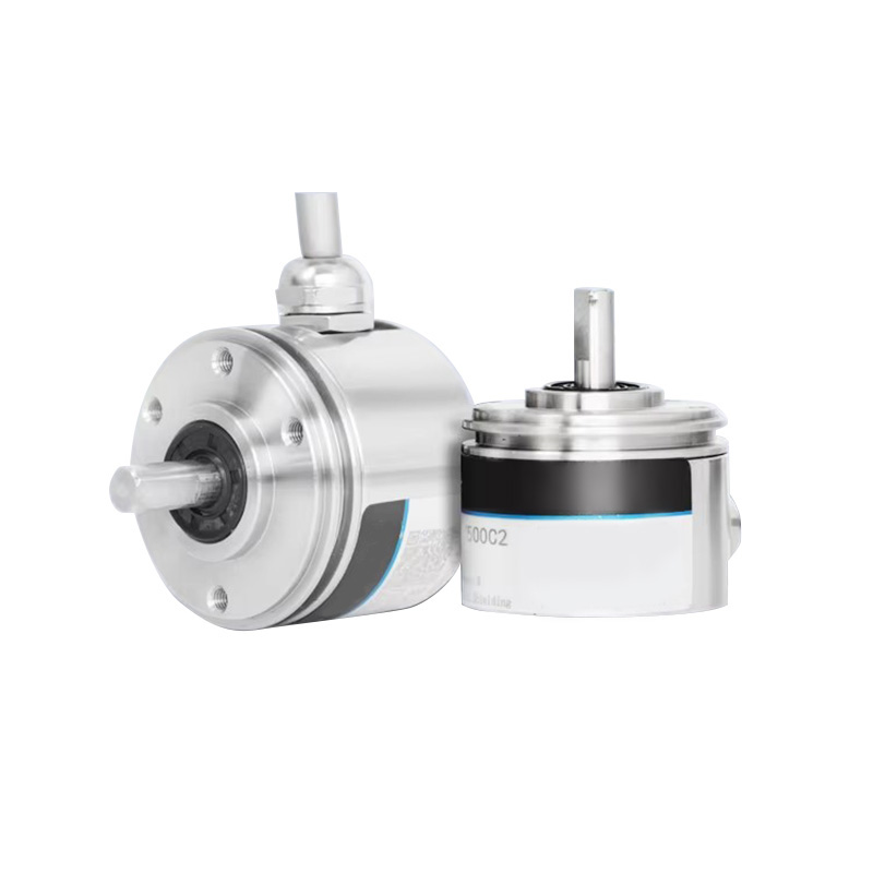
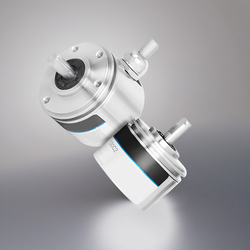
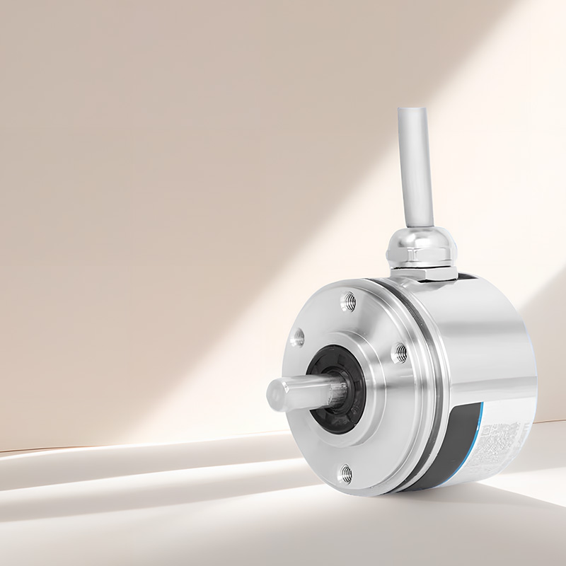
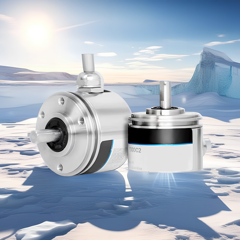
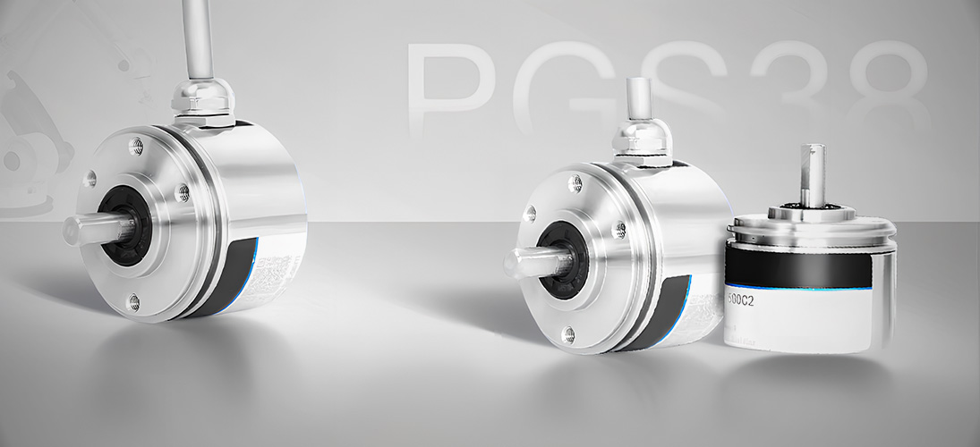
The PGS38 incremental photoelectric encoder is a solid shaft stainless steel design with a variety of electrical interfaces and resolutions to choose from. The highest protection level is IP67. It is compact, sturdy, and highly safe. It is widely used in industrial automation fields with poor environments.
Product Features |
|
Product parameters
Project | Basic parameters | |
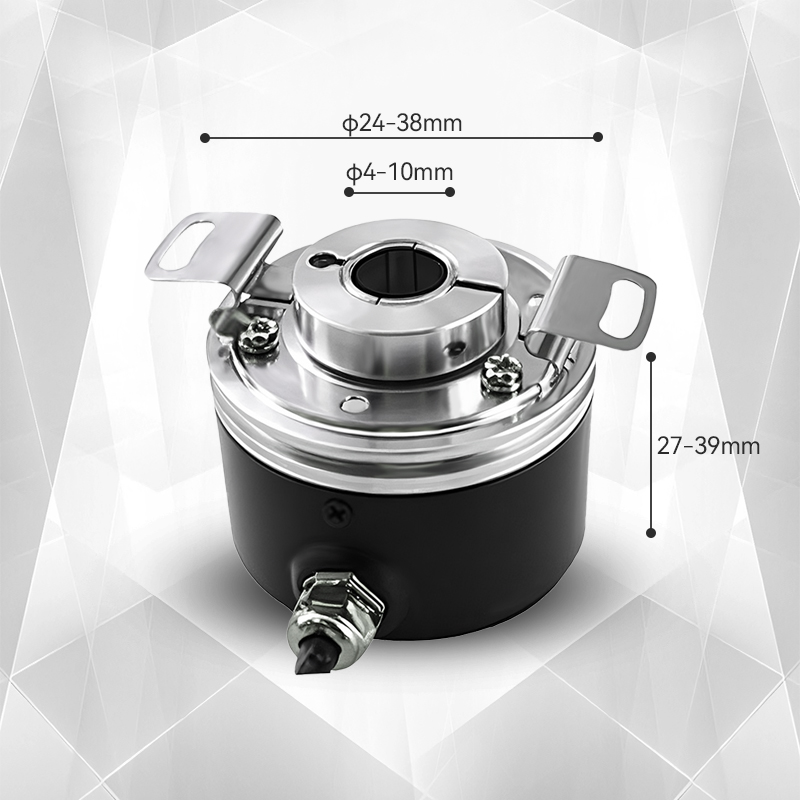
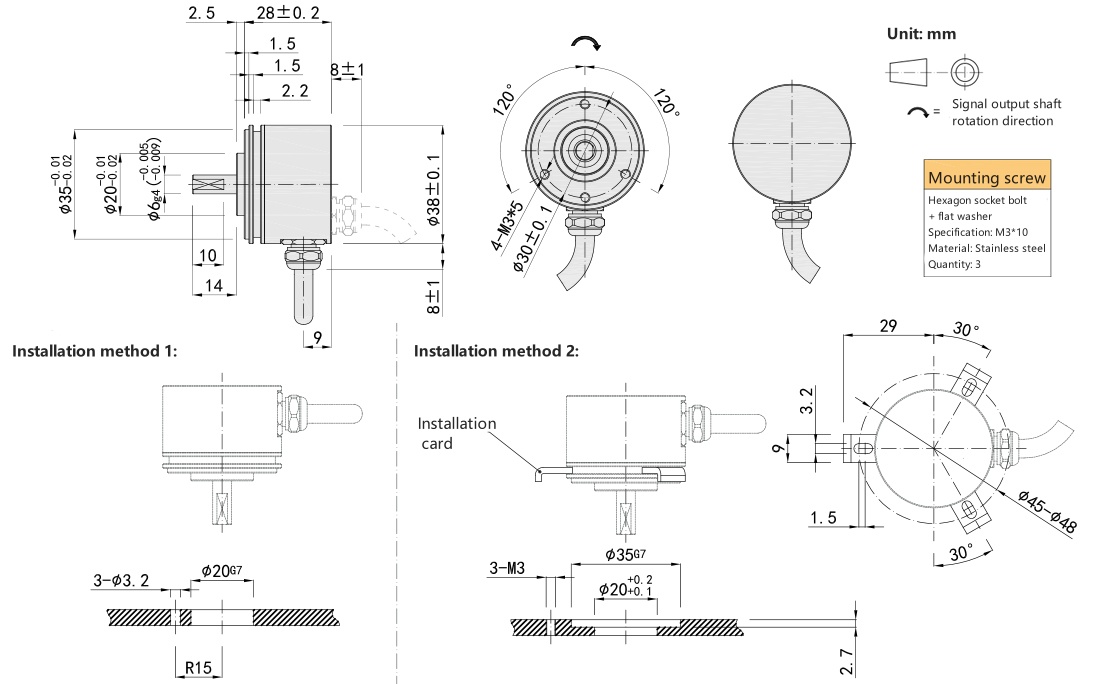
Dimensions | Outer diameter: 38mm | |
Thickness: 28mm | ||
Shaft diameter: 6mm | ||
Pulse | 360;400;500;512;600;1000;1024;2000;2048;2500;5000; | |
Output phase | Phase A,B,Z,A-,B-,Z- | |
Power supply voltage | DC5V & DC8-30V | |
Output mode | Radial cable | |
Axial cable | ||
Output type | NPN&PNP | |
Voltage output | ||
Push-pull output | ||
Differential output | Long line driver (TTL) | |
Long line driver (HTL) | ||
Ambient temperature | Working temperature: -40~+95° (non-condensing) | |
Storage temperature: -40~+95° (non-condensing) | ||
Ambient humidity | Working and storage: 35~85%RH (non-condensing) | |
Maximum speed | ≤6000RPM, IP65≤4000RPM | |
Protection level | IP67 | |
Line length | 1M (cable length can be extended according to customer requirements) | |
Casing | Die-cast aluminum alloy | |
Packing method | Stainless steel | |
Weight | 160g | |
Instructions
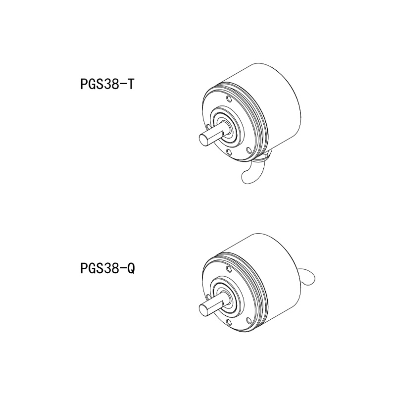
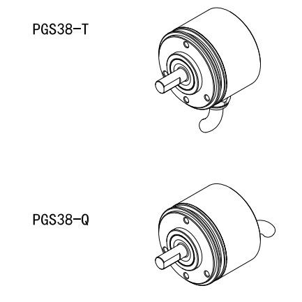
1. Selection guide
Model composition (selection parameters)
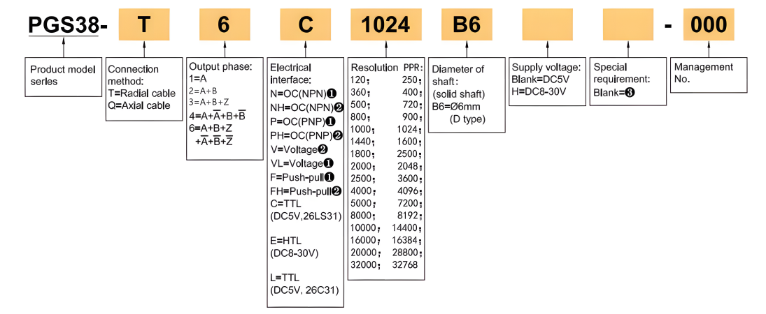
Note:
①. The Z phase signal is valid at low level.
②. The Z phase signal is valid at high level.
③. None means IP67, cable length 1M, if you need to change the length, C+number (up to 100M, such as C100)
2. Output mode
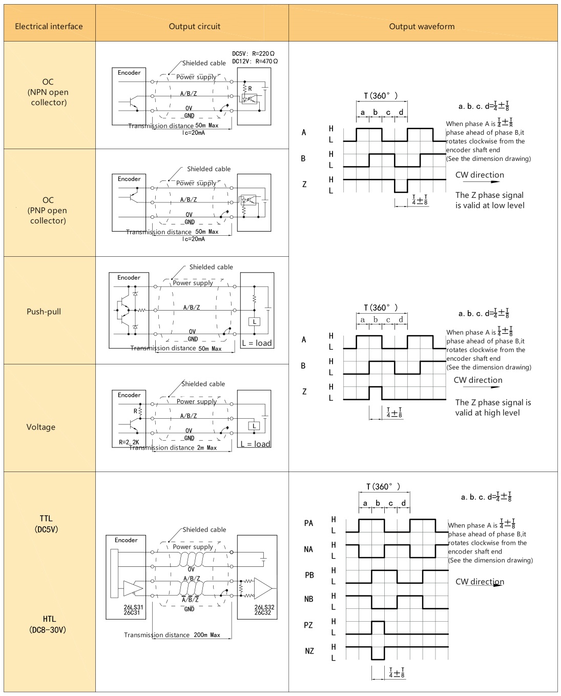
3. Electrical parameters
Project | Output method | ||||||
OC | Voltage | Push-pull | TTL | HTL | |||
Supply voltage | DC+5V±5% ; DC8-30V±5% | DC+5V±5% | DC8-30V±5% | ||||
Current consumption | 100mA Max | 120mA Max | |||||
Allowable ripple | ≤3% rms | ||||||
Maximum response frequency | 100KHz | 500KHz | 800KHz | ||||
Output capacity | Output | Inflow | ≤30mA | Load resistance 2.2K | ≤30mA | ≤±20mA | ≤±50mA |
Outflow | — | ≤10mA | |||||
Output | "H" | — | — | ≥[(power supply voltage)-2.5V] | ≥2.5V | ≥Vcc-3 VDC | |
"L" | ≤0.4V | ≤0.7V(20mA or less) | ≤0.4V(30mA) | ≤0.5V | ≤1 VDC | ||
Load voltage | ≤DC30V | — | — | ||||
Rise and fall time | 2us or less (wire length: 2m) | 1μs or less (wire length: 2m) | |||||
Insulation withstand voltage | AC500V/60s | ||||||
Insulation impedance | 10MΩ | ||||||
Duty cycle | 45%~55% | ||||||
Reverse polarity protection | ✔ | ||||||
Short circuit protection | — | ✔① | |||||
A.B Phase Difference | 90°±10° (at low frequency) | ||||||
90°±20° (at high frequency)) | |||||||
Shielded wire | Encoder body not connected | ||||||
Note: ① Short circuit with another cable or GND, the maximum allowed time is 30 seconds | |||||||
4. Mechanical specifications
Project | Parameter |
Shaft diameter | Φ6mm (D-shaped port, stainless steel) |
Starting torque | 9.8×10⁻³ N・m or less |
Moment of inertia | 6.5×10⁻⁶ kg・m² or less |
Allowable shaft force | Radial 30N; Axial 20N |
Maximum allowable speed | ≤6000 rpm |
Bearing life | Rated load 1.5×10⁹, 100,000 hours at 2500RPW |
Housing | Stainless steel |
Weight | Approx. 160g |
5. Environmental parameters
Project | Parameter |
Ambient temperature | Operating: -40~+95°C(repeated bending cable: -10°C); Storage:-40~+95°C |
Ambient humidity | Operating/Storage: 35~85% RH (non-condensing) |
Vibration (durability) | Amplitude 0.75mm, 5~55Hz, 2h each in three axes |
Shock (durability) | 490m/s², 11ms, 3 times each in X/Y/Z directions |
Protection level | IP67 |
6. Wiring table
6.1 OC/Voltage/Push-PulI
Supply voltage | Incremental signal | ||||
Line color | Red | Black | White | Green | Yellow |
Function | Up | OV | A | B | Z |
6.2 TTL/HTL
Supply voltage | Incremental signal | |||||||
Line color | Red | Black | White | White / Black | Green | Green/Black | Yellow | Yellow/Black |
Function | Up | OV | A+ | A- | B+ | B- | Z+ | Z- |
Twisted Pair | |  | | | ||||
Up = power supply voltage.
The shielded wire is not connected to the internal circuit of the encoder.

7. Basic dimensions and installation requirements
8. Recommended accessories
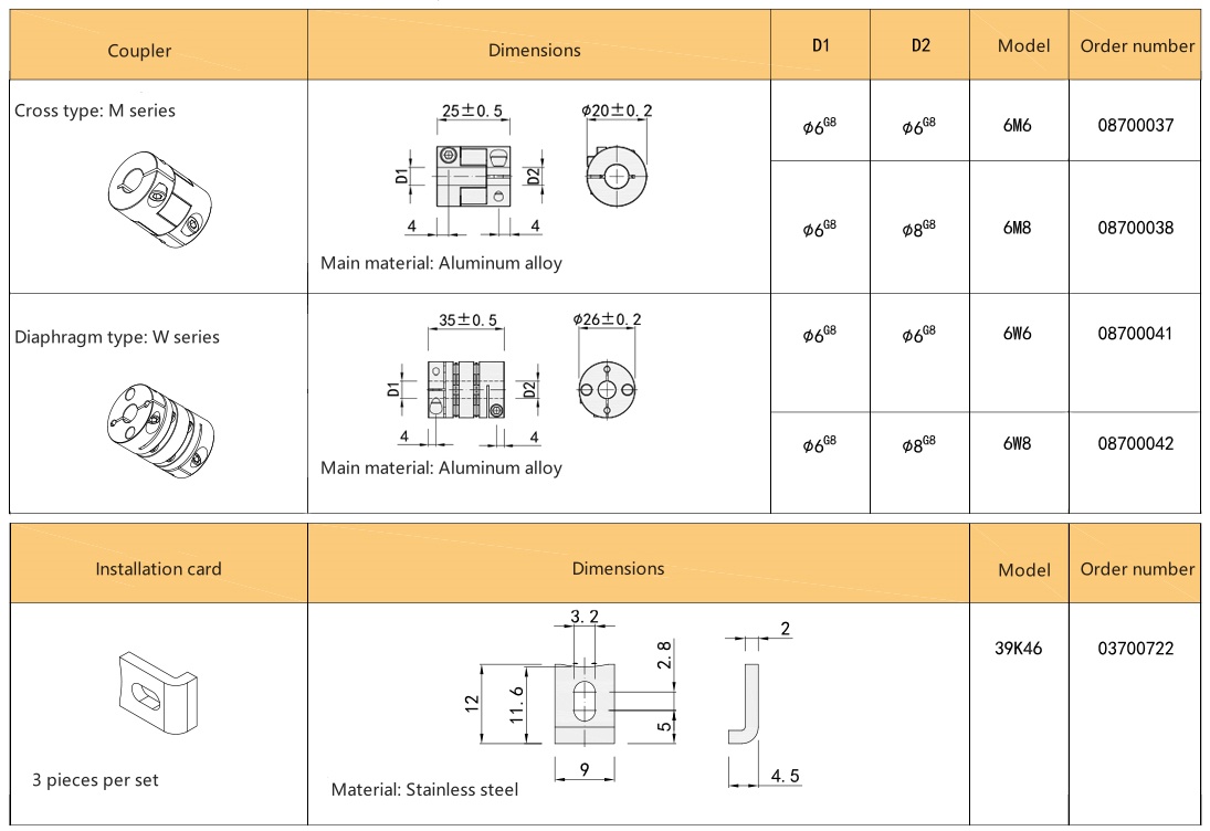
Product Display
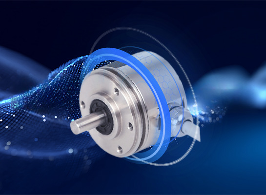
Photoelectric induction, optical path adjustment duty cycle
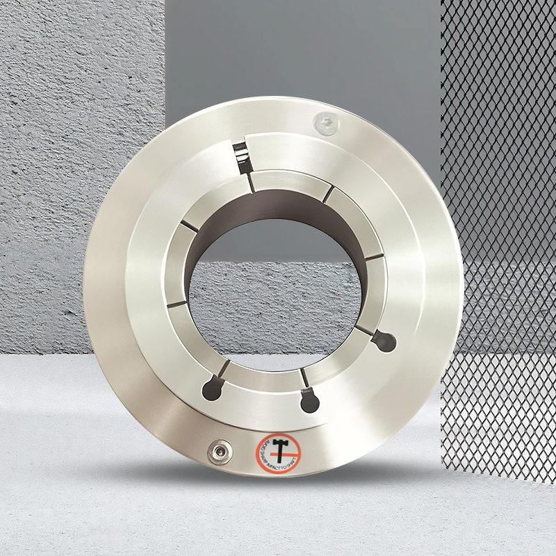
Patented mechanical structure, shaft is not easy to pull out
Flexible spring plate, reduce mechanical damage
Independent grating code disk, high frequency resolution
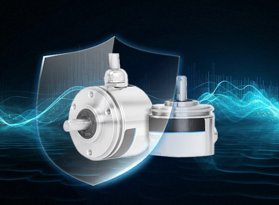
Multiple electrical interfaces, no impact on accuracy
Wide voltage anti-interference, multiple protections
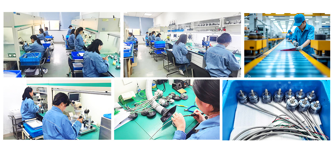
Quality Control
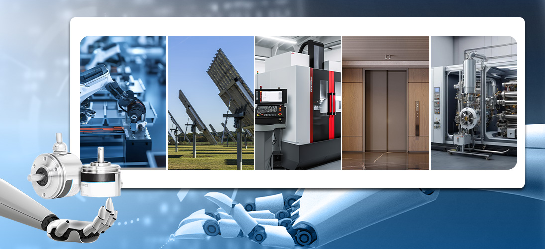
Application Cases
The PGS38 encoder adopts a solid stainless steel shaft design with a protection level of IP67. It is suitable for industrial automation fields with poor environments such as outdoor electromechanical, mining, textile, motor, CNC, etc. It can accurately feedback data through non-contact photoelectric principles, and multiple interfaces and high resolution can meet the control needs of different scenarios.
Service
I. Precautions for using the encoder
Places where the ambient temperature does not exceed the storage temperature; places where the relative humidity does not exceed the storage humidity; places where the temperature changes sharply and fogging occurs; places close to corrosive gases and flammable gases; places away from dust, salt, and metal powder; places where water, oil, and medicines are used; places where excessive vibration and impact will be transmitted to the body
II. Precautions for installing the encoder
Electrical components must not be subjected to overvoltage and other phenomena. Please conduct an electrostatic assessment of the setting environment, etc. Do not bring the motor power line close to the encoder; the FG line of the motor and the FG of the mechanical device must be reliably grounded; due to shielding The wire is not connected to the encoder body. Please make sure that the shielded wire is effectively connected to the ground at the user end.
III. Precautions on wiring
When used under the specified power supply voltage, please pay attention to the power supply voltage amplitude drop caused by the long wiring; please do not use the encoder wire and other power wires in the same pipe or bundle them in parallel; please use twisted pair wires for the signal wire and power wire of the encoder wire; please do not apply excessive force to the encoder harness, there will be a risk of disconnection
IV. About encoder warranty
Within twelve months after purchasing our company's products, users can get free warranty when they use them correctly according to the instructions,warning signs and other precautions and cause failures.
The following situations will be charged even during the warranty period: (freight is at your own expense)
1. Failures and damages caused by the user falling to the ground during transportation and handling, improper installation;
2. Failures of this product caused by the machine connected to it;
3. Failures and damages caused by fire, salt water, corrosive gas, abnormal voltage and other natural disasters such as earthquakes, thunder, wind, floods, etc.;
4. Repairs, adjustments, and modifications without the permission of our company (labels are not there or the outer cover is disassembled by yourself).
5. Failures that occur when the product is not used in accordance with the instructions and precautions in the instruction manual.
6. Except when other agreements are signed with the customer.