
Product Description
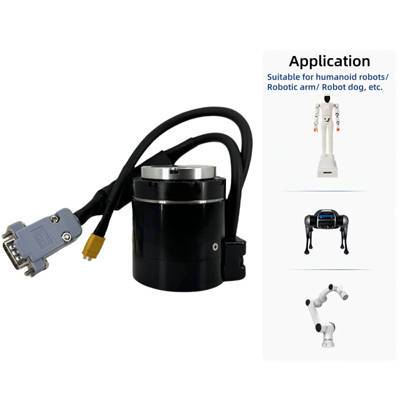
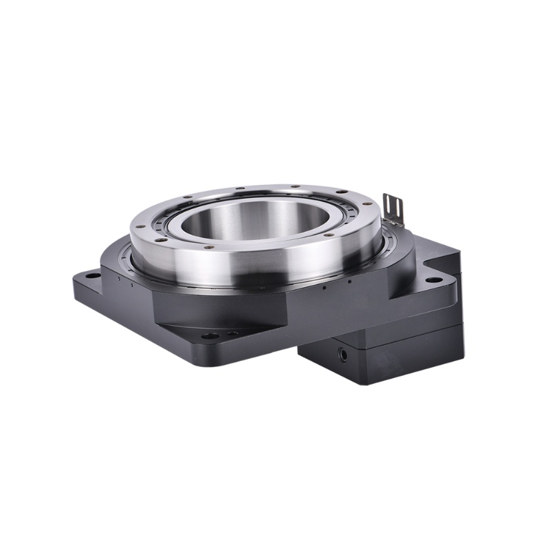
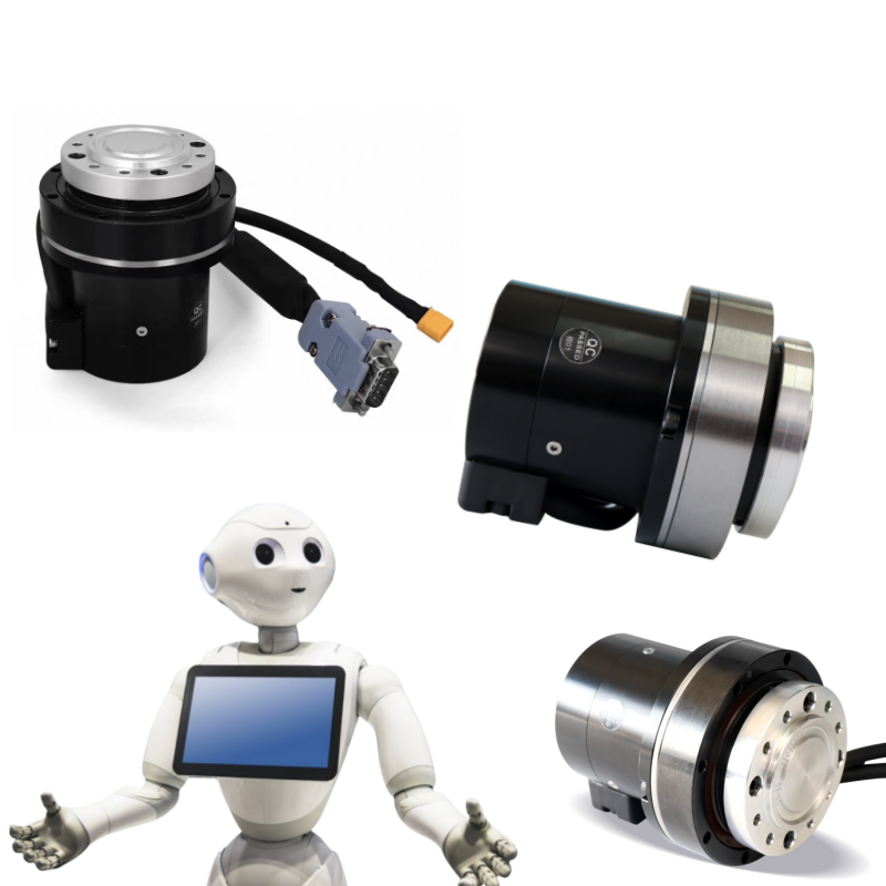
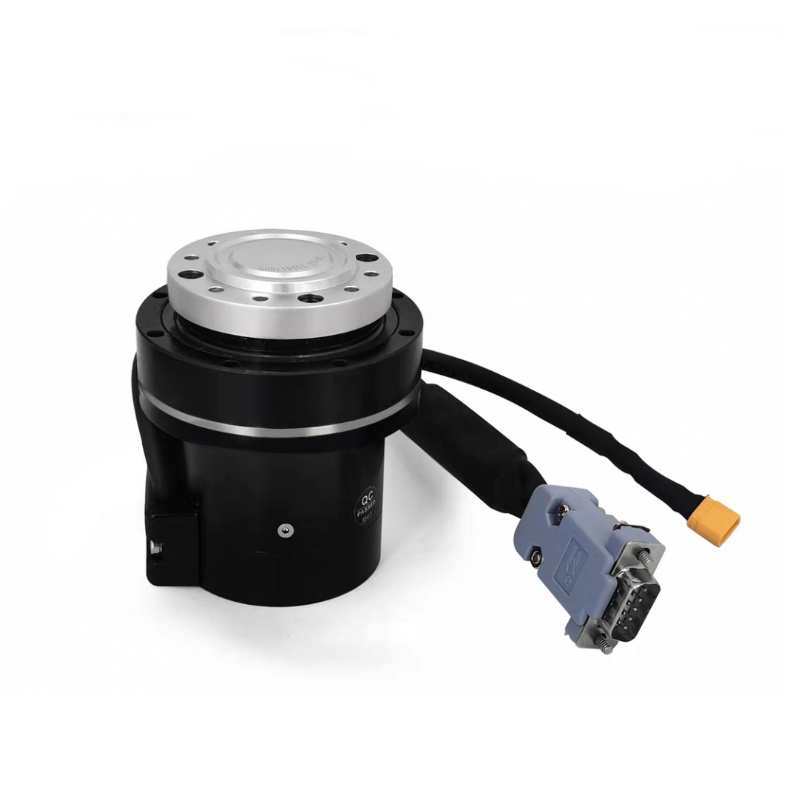
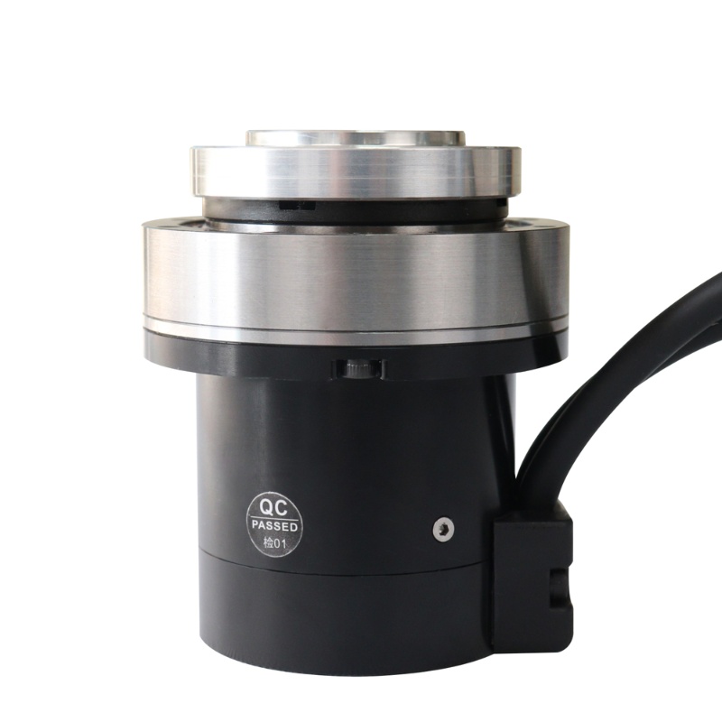
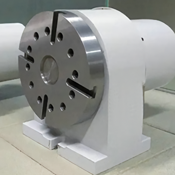
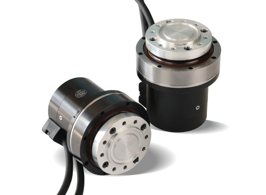
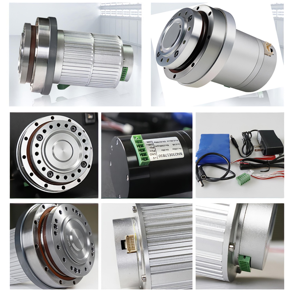
This OD70mm small robot joint actuator servo motor is mainly used for robotic arms. It is integrating harmonic reducer, encoder, DC motor and driver. This robot joint servo motor can be directly used in the joint of the robotic arm to help quickly build the robot joint.
It can be applied in the following fields:
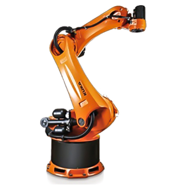
5-Axis Robot Arm
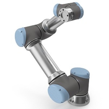
6-Axis Robot Arm
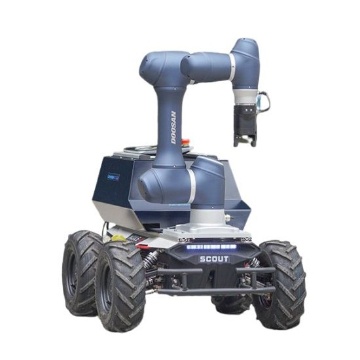
Mobile Robot

Fruit Picking Machinery
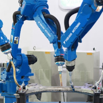
Industrial Service Robot
Turntable
Product Display
Features
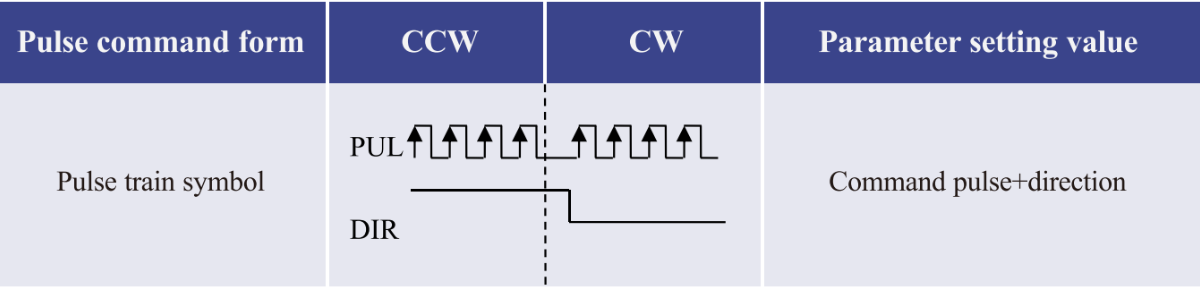
Command pulse + direction position control mode
1. Isolate CANopen communication according to CiA301 V4.2.0 specification
A. Support SDO, TPDO, RPDO.
B. Support speed mode, position mode (contour mode, interpolation mode)
C. Support heartbeat production and consumption
2. 15 bit absolute encoder, one lap pulse up to 32768.
3. Multi-stage DD motor structure, large torque output.
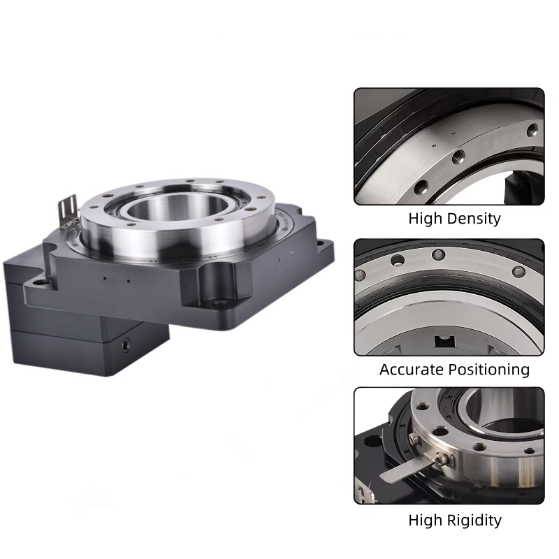
4. Harmonic reducer, motor, driver and encoder are integrated.
5. Low noise, low vibration, high speed positioning, high reliability.
6. FOC field oriented vector control, support position / speed closed loop.
7. Can work at zero hysteresis given pulse state, following zero hysteresis.
8. 16-bit electronic gear features.
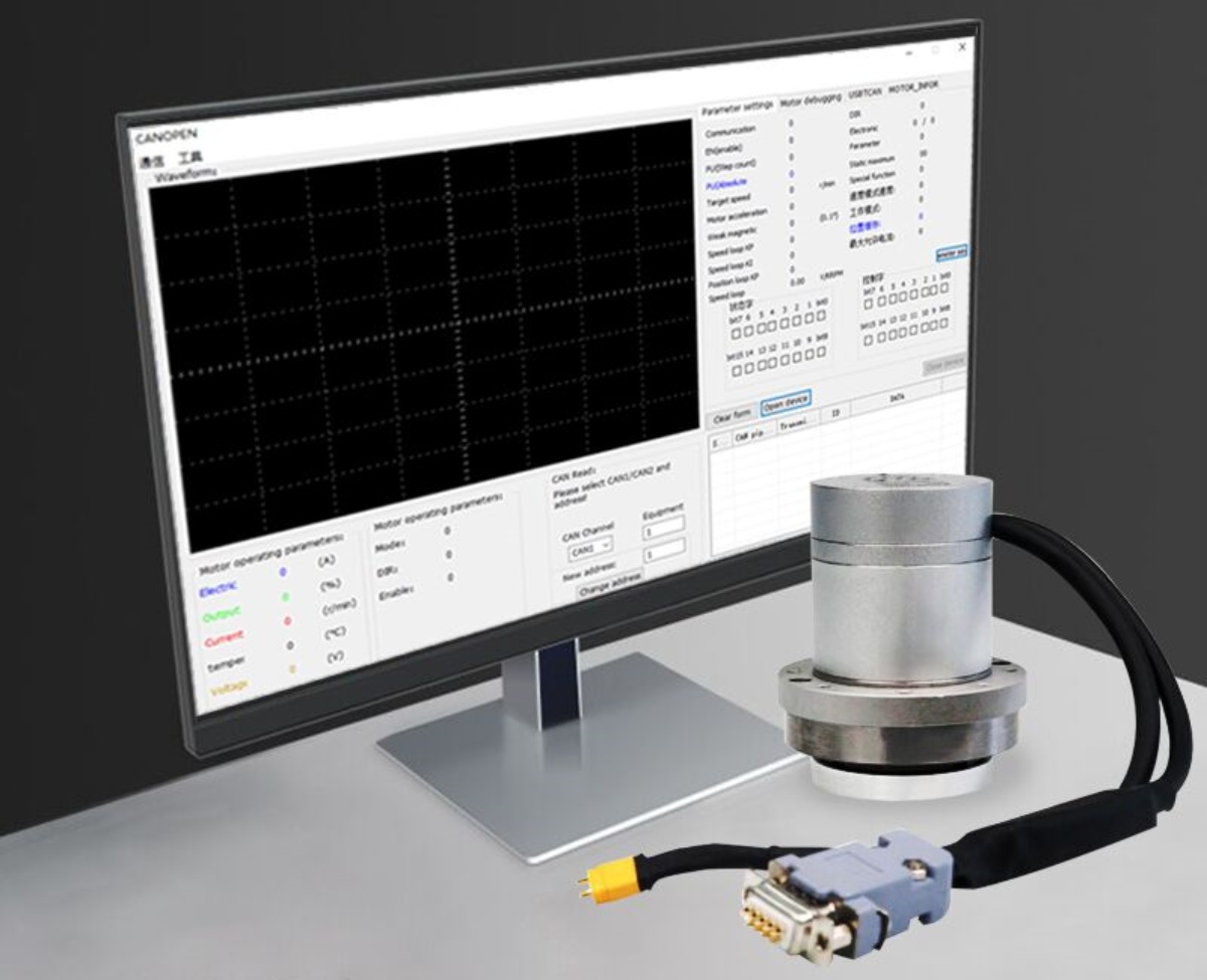
9. CANopen upper computer is provided, which can monitor motor state and modify parameters.
10. Position mode, support pulse + direction signal, encoder to follow.
11. Speed mode, support PWM duty cycle signal speed regulation
12. It has the function of blocking rotation, over current protection and over voltage protection.
13. Absolute value of low power consumption and multi-turn
A. All-in-one servo 485/CAN communication version can add multi-turn function.
B. When the motor is powered, there is a charging circuit inside to charge the battery. When the motor is powered off, the battery current consumption is only 0.07mA.
C. After the motor has no power supply, the motor shaft is driven to rotate to wake up the encoder and continue to memorize the position.
D. Multi-turn memory range -60000 ~ 60000 laps.
E. Simple setting of the origin, it can be set as the origin at any position.
F. Multiple zero return methods: communication zero return, automatic zero return on power-on, and zero point signal output.
G. Error protection: battery power failure alarm.
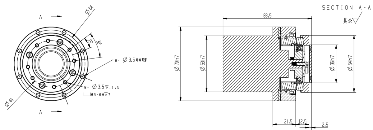
Dimensional drawing
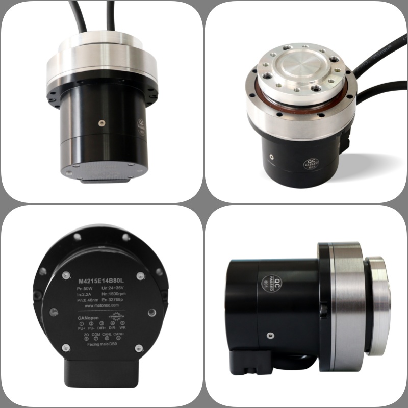
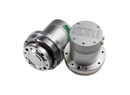
M4215
Product parameters
Parameter | M4210E11BXX | M4215E14BXX | M8010E17BXX | M8025E25BXX | |
Overall parameter | Motor rated voltage | 36VDC±10% | 36VDC±10% | 36VDC±10% | 36VDC±10% |
Motor rated current | 1.5A | 2A | 3.5A | 7A | |
Output torque after deceleration | 3.2NM | 10NM | 34/51/51NM | 51/85NM | |
Weight | 0.4KG | 0.8KG | 1KG | 2.5KG | |
Speed range after deceleration | 0~40RPM | 0~40/0~25/0~20RPM | 0~30/0~18/0~15RPM | 0~30/0~19RPM | |
Reducer parameter | Reduction ratio | 50 | 50/80/100 | 50/80/100 | 50/80 |
Rated torque | 3.2NM | 7/10/10NM | 34/51/51NM | 51/85NM | |
Peak start-stop torque | 7.8NM | 23/30/36NM | 44/70/70NM | 127/178NM | |
Backlash | <10 arc seconds | <10 arc seconds | < 20arc seconds | < 20arc seconds | |
Design life | 8500hour | 8500hour | 8500hour | 8500hour | |
Motor parameter | Torque | 0.3NM | 0.5NM | 1NM | 2NM |
Rated speed | 2000RPM | 1500RPM | 1500RPM | 1000RPM | |
Maximum rotational speed | 2500RPM | 2000RPM | 2000RPM | 1500RPM | |
Power | 33W | 50W | 100W | 200W | |
Resistance | 3.45 | 2.65 | 0.86 | 0.53 | |
Inductance | 1.18mh | 1.1mh | 0.8mh | 0.5mh | |
Rotary inertia | 0.9139x10⁻⁴ KG/M 2 | 0.9139x10⁻⁴ KG/M 2 | 0.69x10⁻⁴ KG/M 2 | 1.74x10⁻⁴ KG/M 2 | |
Parameter | M4210E11BXX | M4215E14BXX | M8010E17BXX | M8025E25BXX | |
Feedback signal | Multi-turn absolute encoder (15 bit single-turn and 16 bit multi-turn) | Multi-turn absolute encoder (15 bit single-turn and 16 bit multi-turn) | Multi-turn absolute encoder (15 bit single-turn and 16 bit multi-turn) | Multi-turn absolute encoder (15 bit single-turn and 9 bit multi-turn) | |
Cooling mode | Natural cooling | Natural cooling | Natural cooling | Natural cooling | |
Position Control Mode | Maximum input pulse frequency | 500KHz | 500KHz | 500KHz | 500KHz |
Pulse instruction mode | Pulse + direction, A phase +B phase(needs the controller supports AB pulses) | Pulse + direction, A phase +B phase(needs the controller supports AB pulses) | Pulse + direction, A phase +B phase(needs the controller supports AB pulses) | Pulse + direction, A phase +B phase(needs the controller supports AB pulses) | |
Electronic gear ratio | Set up 1~65535 to 1~65535 | Set up 1~65535 to 1~65535 | Set up 1~65535 to 1~65535 | Set up 1~65535 to 1~65535 | |
Location sampling frequency | 2KHZ | 2KHZ | 2KHZ | 2KHZ | |
Protection function | Lock-motor alarm, over-current alarm | Lock-motor alarm, over-current alarm | Lock-motor alarm, over-current alarm | Lock-motor alarm, over-current alarm | |
Communication interface | Canopen (CAN Communication) /Modbus(485 communication) | Canopen (CAN Communication) /Modbus(485 communication) | Canopen (CAN Communication) | Canopen (CAN Communication, rate 1M) | |
Environment | Ambient temperature | 0~40° | 0~40° | 0~40° | 0~40° |
Max. permissible temperature of motor | 85° | 85° | 85° | 85° | |
Humidity | 5~95% | 5~95% | 5~95% | 5~95% | |
Interface definition
Power connector
Terminal Serial No. | Name | Function |
1 | +V | Positive DC Power +24V~36V. Negative and positive connections can either directly short the power supply or damage the driver |
2 | GND | DC power source. Negative and positive connections can either directly short the power supply or damage the driver |
Communication and output interface
For CANOPEN communication protocol
DB9 Male head | |||||||||
1 | 2 | 3 | 4 | 5 | 6 | 7 | 8 | 9 | |
PU+ | PU- | DIR+ | DIR- | WR+ | ZO | COM | CANL | CANH | |
BLUE | BLUE BLACK | GREEN | GREEN BLACK | RED WHITE | YELLOW | BLACK WHITE | BROWN | WHITE | |
Terminal serial number | Name | Function |
1 | PU+ | Pulse control signal: the rising edge of the pulse is valid; PU- is 3.3~5V at high level, and 0~0.5V at low level. For reliable response to pulsed signals, the pulse width should be greater than 1.2μs. If +12V or +24V is used, a series resistor is required. |
2 | PU- | |
3 | DIR+ | Direction signal: high/low level signal, in order to ensure the reliable commutation of the motor, the direction signal should be established at least 5μs before the pulse signal. DIR-3.3~5V at high level, 0~0.5V at low level. |
4 | DIR- | |
5 | WR+ | Alarm signal output, the internal output is optocoupler NPN. Normally, it is in high impedance state, and it is connected to COM during alarm. |
6 | ZO | Encoder zero output. There is a zero signal optocoupler NPN output conduction signal. |
7 | COM | The output signal is common to the 485 power supply. |
8 | CANL | Can Communication port CANL, built-in isolated power supply. |
9 | CANH | Can Communication port CANH, built-in isolated power supply. |
For MODBUS communication protocol
DB9 Male head | |||||||||
1 | 2 | 3 | 4 | 5 | 6 | 7 | 8 | 9 | |
PU+ | PU- | DIR+ | DIR- | WR+ | ZO | COM | CANL | CANH | |
BLUE | BLUE BLACK | GREEN | GREEN BLACK | RED WHITE | YELLOW | BLACK WHITE | BROWN | WHITE | |
Terminal serial number | Name | Function |
1 | PU+ | Pulse control signal: the rising edge of the pulse is valid; PU- is 3.3~5V at high level, and 0~0.5V at low level. For reliable response to pulsed signals, the pulse width should be greater than 1.2μs. If +12V or +24V is used, one resistor is required. |
2 | PU- | |
3 | DIR+ | Direction signal: high/low level signal, in order to ensure the reliable commutation of the motor, the direction signal should be established at least 5μs before the pulse signal. DIR-3.3~5V at high level, 0~0.5V at low level. |
4 | DIR- | |
5 | WR+ | Alarm signal output, the internal output is optocoupler NPN. Normally, it is in high impedance state, and it is connected to COM during alarm. |
6 | ZO | Encoder zero output. There is a zero signal optocoupler NPN output conduction signal. |
7 | COM | The output signal is common to the 485 power supply. |
8 | 485A | 485 Communication port A, built-in isolated power supply. |
9 | 485B | 485 Communication port B, built-in isolated power supply. |
FAQ
Q1: What communication protocols does the M series support?
A: The M series supports isolated CANopen (CiA301 V4.2.0), RS485, EasyCAN and other protocols, and can be switched and configured through the host computer.
Q2: Can the current position be remembered after power failure?
A: Yes, the M series supports low-power multi-turn absolute encoder (with battery version). The rotation of the drive shaft can still be recorded after power failure and automatically restored after power-on.
Q3: How to set the origin of the motor?
A: The origin can be set through communication, automatically return to zero after power-on, or quickly set through the zero point signal. Users can flexibly choose according to the application scenario.
Q4: Is an external driver required?
A: No, the M series is a highly integrated integrated servo module with built-in motor, encoder and driver, and users do not need additional configuration.
Q5: Does it support overload protection?
A: Yes, the M series has stall protection, overcurrent protection, overvoltage protection, and can monitor the status through the host computer to ensure safe operation.