

Product Description
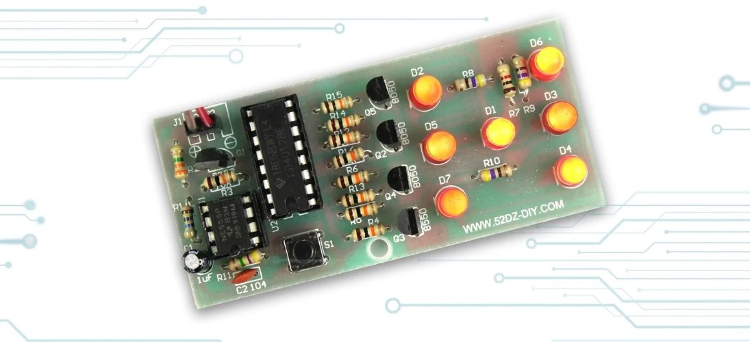
Fun Kit
Simple
Guessing Dice Game Electronic Kit
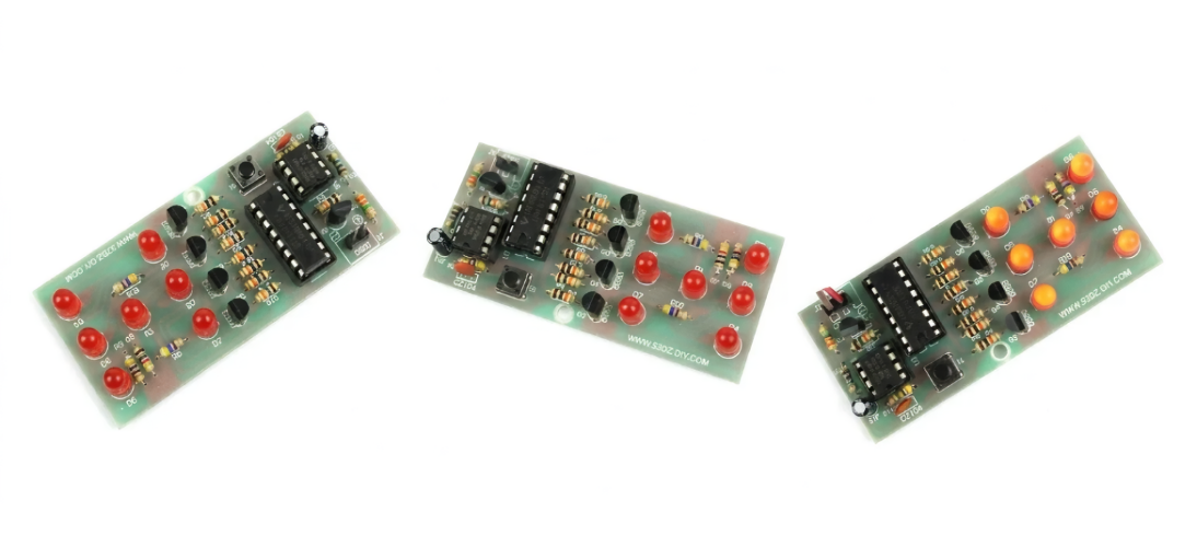
When powered on, the 7 LEDs will randomly display a point value. When the player presses switch S1,
all 7 LEDs will turn on. After a few seconds, the 7 LEDs will start flashing until a stable point value
is finally displayed.
Available in five LED light colors
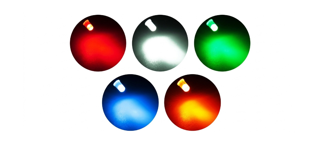
Red light White light Green light
Blue light Yellow light
Product Dimensions
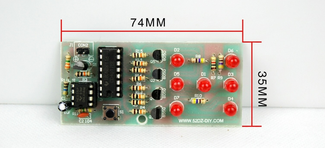
Measured manually; a margin of error of 1–2 cm is considered normal
Product parameters
Parameter | Value |
Product Name | Guessing Dice Game Props Electronic Kit |
Operating Voltage | DC 5V |
Dimensions | 74mm x 35mm |
PCB Material | Double-sided 1.6mm FR-4 Board |
LED Colors | Red / White / Yellow / Blue / Green |
LED Quantity | 7 Pcs |
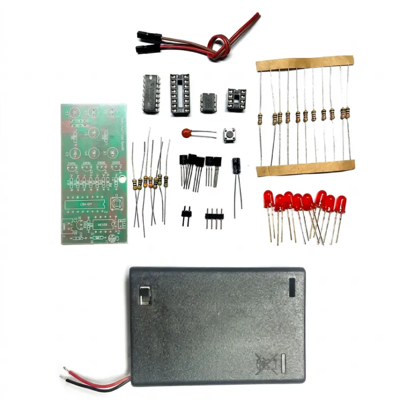
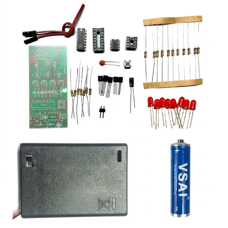
List of Original Documents
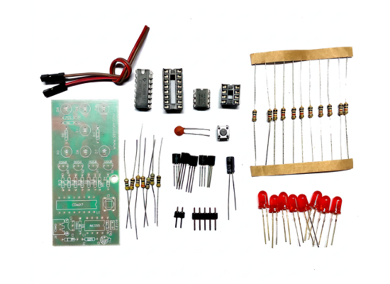
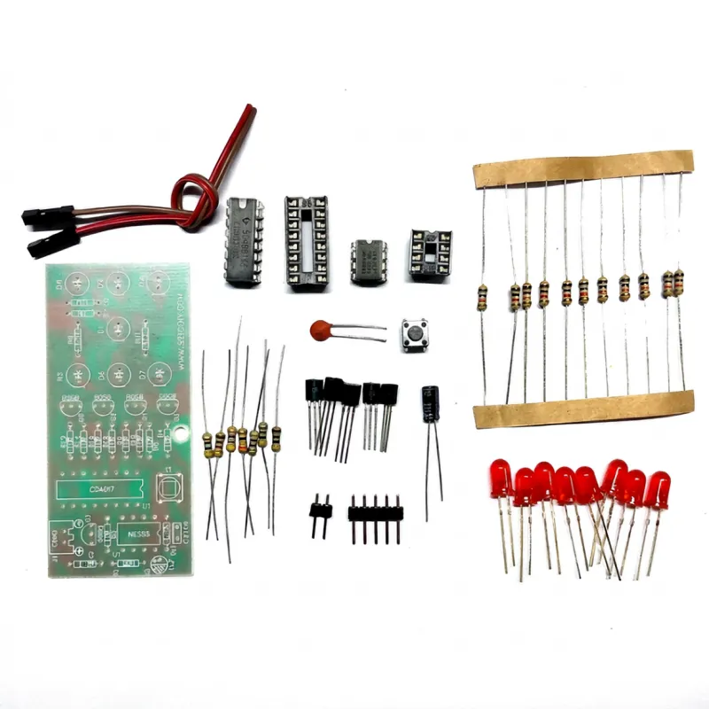
Component Name | Parameter / Value | PCB Marking |
Resistor | 470R | R8, R9, R10 |
1K | R7 | |
10K | R3-R6, R12-R16 | |
3.3M | R2 | |
4.7M | R11 | |
10M | R1 | |
Capacitor | 104P | C2 |
1uF / 50V | C1 | |
LED | 5mm Red | D1-D7 |
Tact Switch | 6*6*5 | S1 |
Transistor | S8050 | Q2, Q4, Q5 |
S8550 | Q1, Q3 | |
Integrated Circuit | NE555 | U1 |
CD4017 | U2 | |
Terminal Connector | XH2.54 2P Vertical | J1 |
Power Cable | XH 2P Single Head | 1 |
PCB Board | FR-4 | 35mm * 74mm |
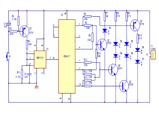
Schematic diagram
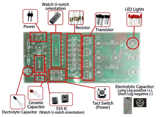
1. The PCB is printed with component silkscreen markings; please solder according to these markings.
2. Resistors have no polarity, but they have different resistance values. Please make sure to distinguish them during soldering.
3. Electrolytic capacitors and LED lights have positive and negative polarities. The long leg is positive (+), and the short leg is negative (-).
4. When connecting the power line to the terminal block, pay attention to the positive and negative polarities to avoid reverse connection.