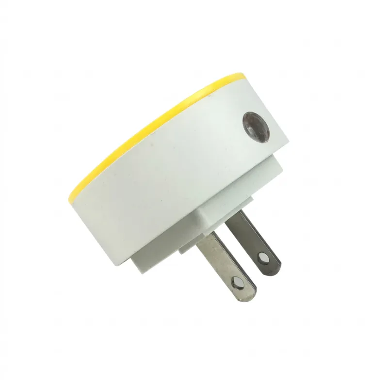




Product Description
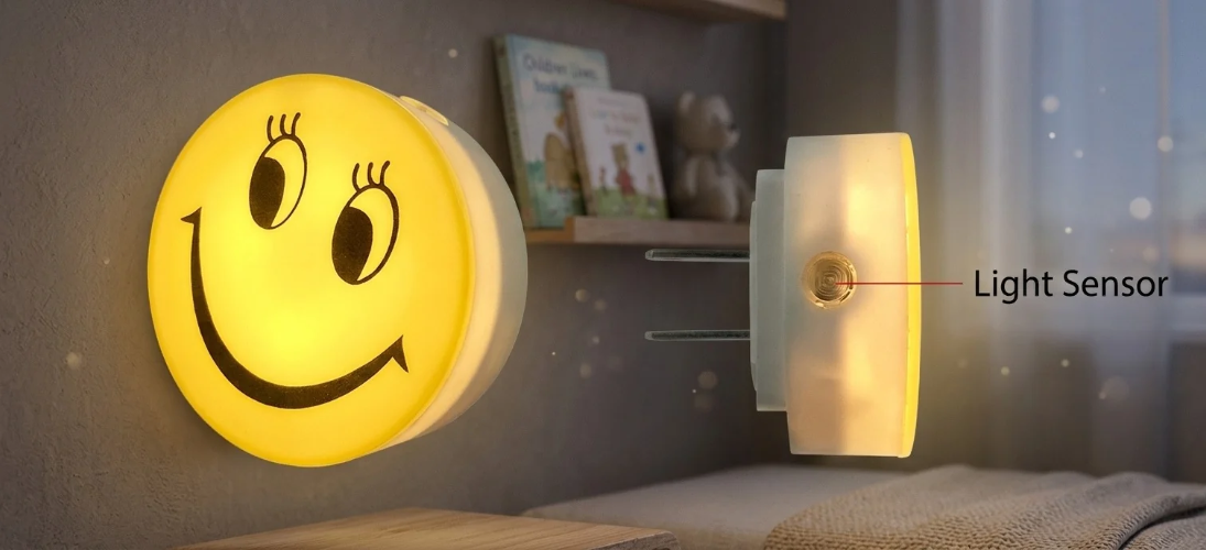
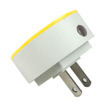
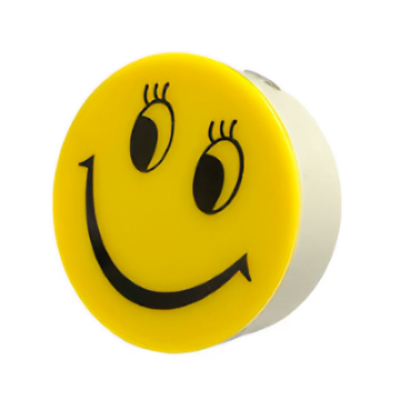
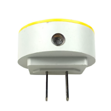
Smart Light-Controlled LED Night Light
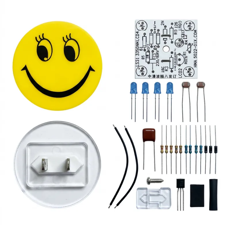
Electronic DIY Kit
1. During the day when the light is strong, the photoresistor is in a low-resistance state. At this time, the base voltage of Q1 is approximately 0V, Q1 is cut off, and the LED light does not emit light.
2. At night when the light becomes dim, the photoresistor is in a high-resistance state. The voltage is applied to the base of Q1 via R4, Q1 conducts, and the LED light emits light.
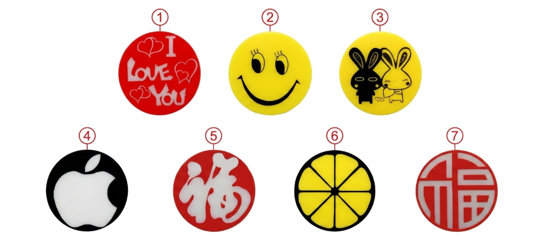
Seven designs available
(Designs are shipped at random. If you would like to request a specific design, please check with customer service for availability before placing your order. If it is in stock, please specify your choice in the order notes!)
Dimensional Drawin
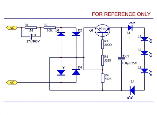
Schematic Diagram
Circuit Diagram Display
Circuit Principle:
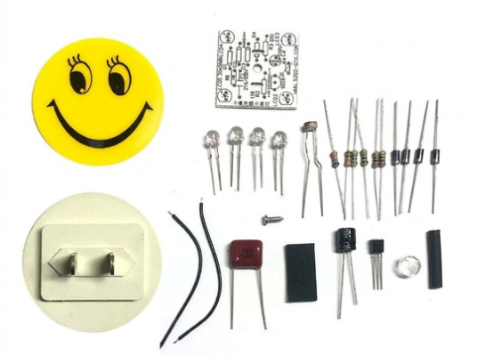
R1 and C1 form a capacitive step-down circuit (non-isolated step-down), and R2 acts as current-limiting. D1-D4 form a bridge rectifier circuit, and D5 stabilizes the voltage at 24V. Q1 serves as the switching adjustment transistor for the LED load (L1-L4), and C2 provides filtering.
Product parameters
Component List | ||||
Component Introduction & PCB Location | ||||
Name | Image | Model / Specification | PCB Designation | Quantity |
Resistor | Red, black, brown, gold | 200 | R3 | 1 |
Brown, black, orange, gold | 10K | R2 | 1 | |
Brown, black, green, gold | 1M | R1 | 1 | |
Photoresistor |
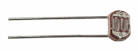
| 5528 | R4 | 1 |
Capacitor |
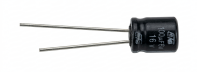
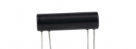
| 100uF / 25V | C2 | 1 |
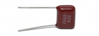
| 274 / 400VP | C1 | 1 | |
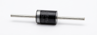
Diode |
| 1N4007 | D1-D4 | 4 |
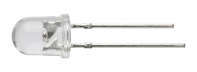
LED |
| F5 Straw Hat White Light | L1-L4 | 4 |
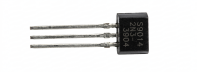
Transistor |
| 9014 | Q1 | 1 |
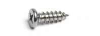
Screw |
| M2.3*6 | 1 | 1 |
Heat Shrink Tube |
| F3*10mm | 1 | 1 |
PCB |
| 30*30mm | 1 | 1 |
Top Cover | 50*50mm | 1 | 1 | |
Bottom Cover | 50*88mm | 1 | 1 | |
Lens Cover |
| - | 1 | 1 |


Application wiring diagram
Product Details / Assembly Instructions
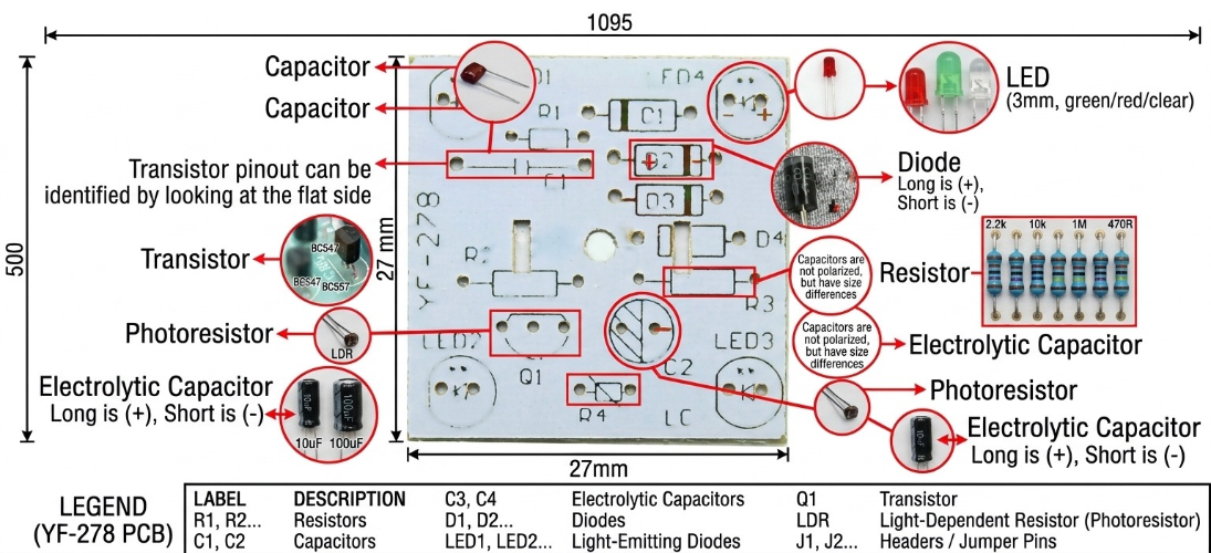
1. Silkscreen Markings: The PCB is printed with silkscreen markings for various components. Please solder them by matching the components to their corresponding silkscreen labels.
2. Resistors: Resistors are non-polarized (no direction required), but they have different resistance values. Please pay attention to distinguish them during soldering.
3. Electrolytic Capacitors: Electrolytic capacitors are polarized. The long lead is positive (+), and the short lead is negative (-). Pay attention to the silkscreen polarity direction on the PCB when soldering.
4. Power Cord Connection: When connecting the power cord to the terminal block, pay attention to the positive and negative poles, and make sure not to reverse them.
5. Diodes: Pay attention to the correct direction/polarity of the diodes.
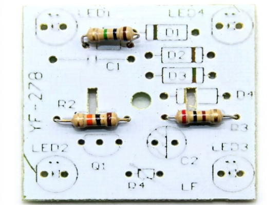
1. Solder the 3 resistors; pay attention to their resistance values and ensure they are soldered in the correct locations. It is recommended to mount them flush against the PCB.
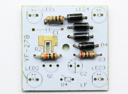
2. Next, solder the four diodes. Pay attention to their polarity during soldering; the end with the white band is the cathode. The PCB features corresponding silkscreen markings to guide proper placement.
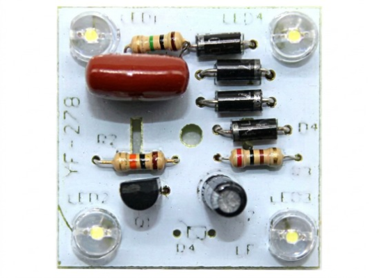
3. Next, solder the electrolytic capacitor, the transistor, and the CBB capacitor in place. Both the transistor and the electrolytic capacitor are polarized components; be sure to observe the correct polarity (positive and negative terminals) when soldering.
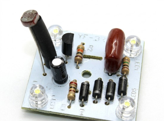
4. Solder the photoresistor. When soldering, be sure to slide a piece of heat-shrink tubing onto one of the photoresistor's leads, as shown in the figure below.
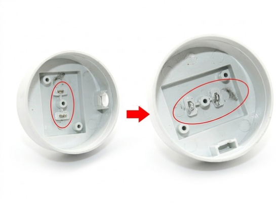
5. Next, apply solder to the two pins on the night light’s base cover to facilitate the connection of the power cord.
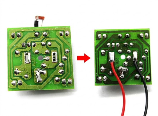
6. Solder two power wires onto the underside of the board.
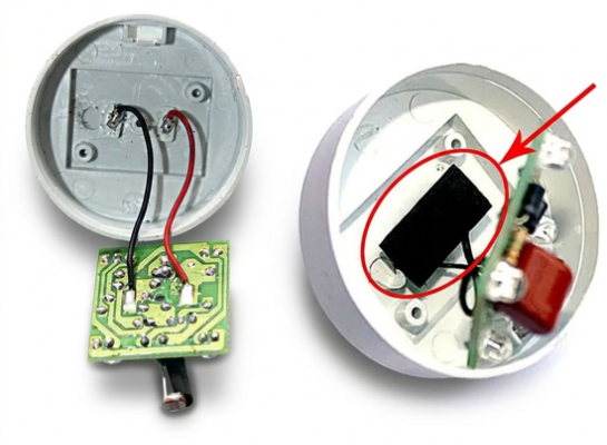
Note: Apply a foam pad here to prevent the metal piece
from short-circuiting the PCB (no screws are required).
7. Finally, solder the power cord—which has already been soldered—onto the bottom cover.