Robot gift store
  • Electronic Dice DIY Soldering Kit Fun LED Lucky Dice Teaching and Training Production Loose Parts TJ-56-40
  • Electronic Dice DIY Soldering Kit Fun LED Lucky Dice Teaching and Training Production Loose Parts TJ-56-40
  • Electronic Dice DIY Soldering Kit Fun LED Lucky Dice Teaching and Training Production Loose Parts TJ-56-40
  • Electronic Dice DIY Soldering Kit Fun LED Lucky Dice Teaching and Training Production Loose Parts TJ-56-40
  • Electronic Dice DIY Soldering Kit Fun LED Lucky Dice Teaching and Training Production Loose Parts TJ-56-40
  • Electronic Dice DIY Soldering Kit Fun LED Lucky Dice Teaching and Training Production Loose Parts TJ-56-40
  • Electronic Dice DIY Soldering Kit Fun LED Lucky Dice Teaching and Training Production Loose Parts TJ-56-40
  • Electronic Dice DIY Soldering Kit Fun LED Lucky Dice Teaching and Training Production Loose Parts TJ-56-40
  • Electronic Dice DIY Soldering Kit Fun LED Lucky Dice Teaching and Training Production Loose Parts TJ-56-40
  • Electronic Dice DIY Soldering Kit Fun LED Lucky Dice Teaching and Training Production Loose Parts TJ-56-40

Electronic Dice DIY Soldering Kit Fun LED Lucky Dice Teaching and Training Production Loose Parts TJ-56-40

Electronic Dice DIY Soldering Kit TJ-56-40 teaches basic electronics and soldering skills through hands-on assembly, featuring LED lights for interactive learning and fun.

    USD 0.87

    contact shop

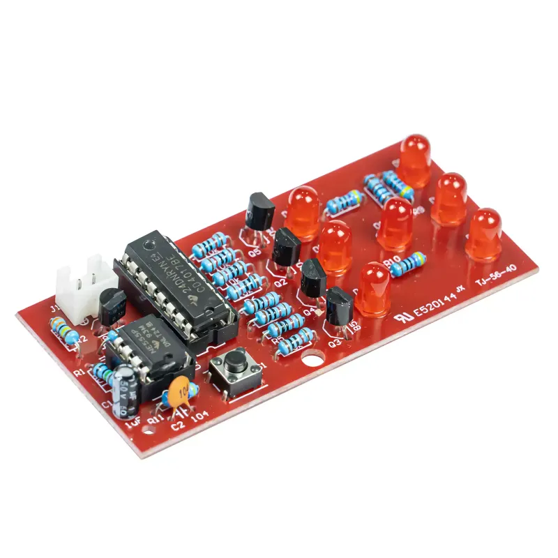
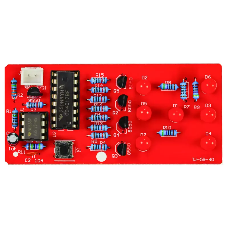
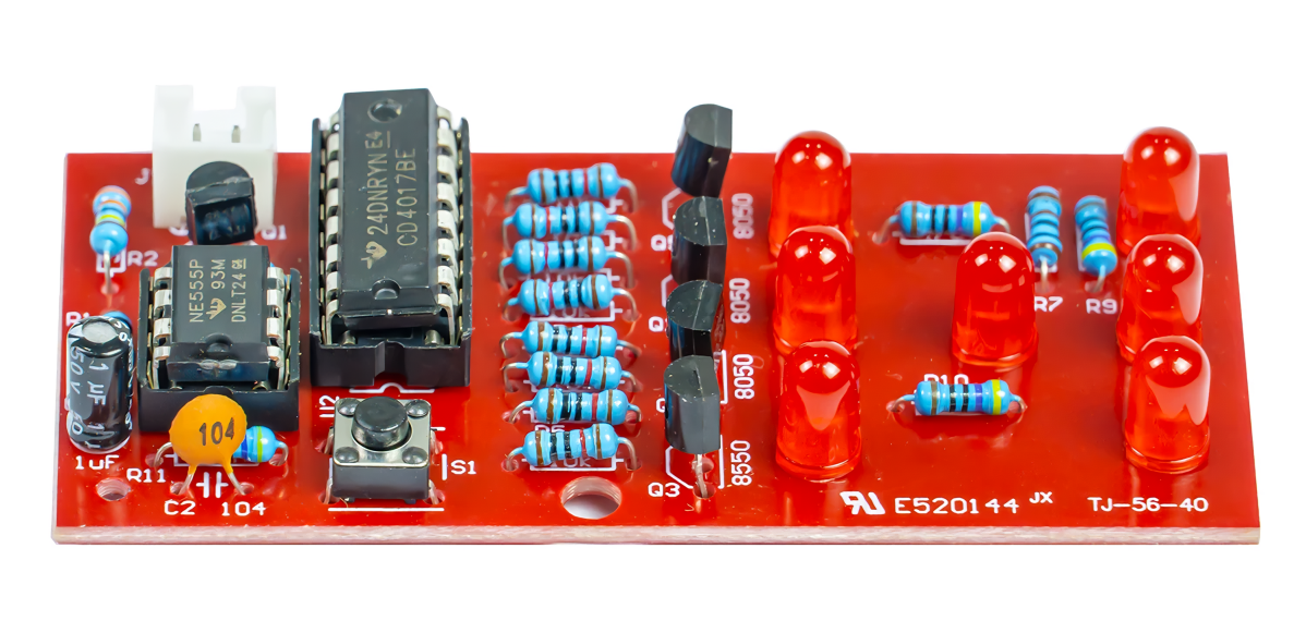
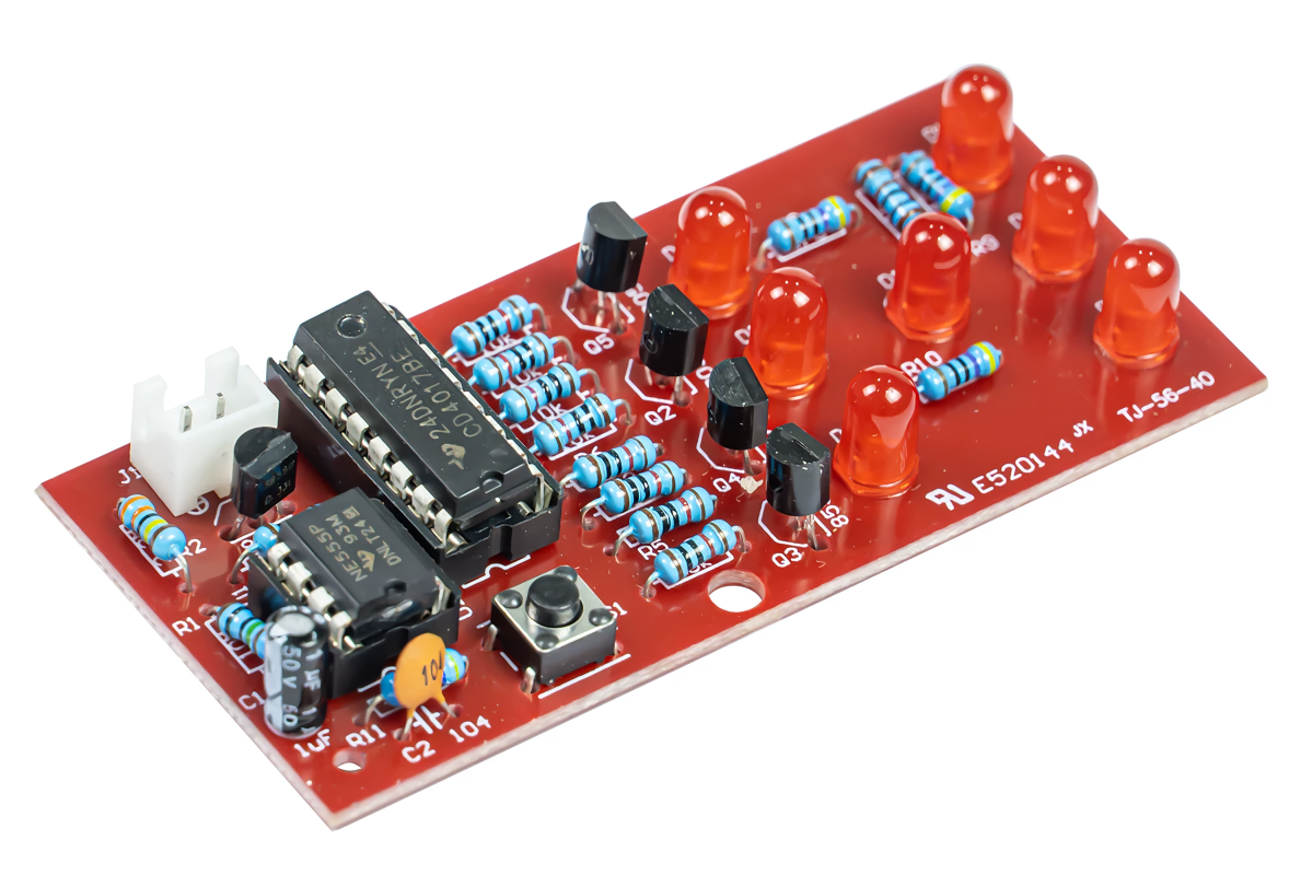
    Product Display


    Kit Parameters

    Product Model

    TJ-56-40

    Supply Voltage

    4.5–6 V (DC power supply)

    Board Dimensions

    75*35mm


    Functional Description

    When the device is powered on, the seven LEDs will randomly display a value. Upon pressing switch S1, all seven LEDs will light up; after a few seconds, they will begin to flash, eventually settling on a stable value. This completes one full "dice roll" cycle.

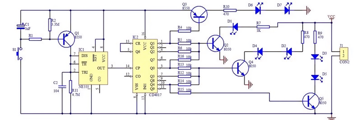
    The circuit primarily consists of a pulse generator and a decimal counter. The pulse generator is an astable multivibrator built using an NE555 timer and peripheral components. When switch S1 is pressed, transistor Q1 turns on, causing pin 3 of the NE555 to output pulses. This triggers the CD4017 decimal counter, which cycles its five output pins to a high state in sequence. Through various combinations of resistors and transistors, these outputs drive the seven LEDs to display a value from 1 to 6.


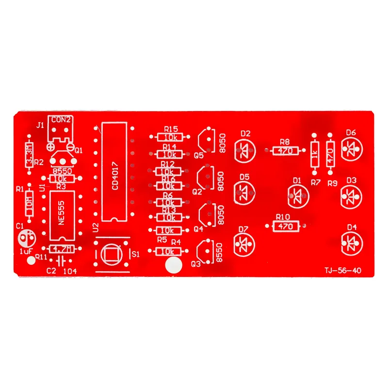
    Circuit diagram
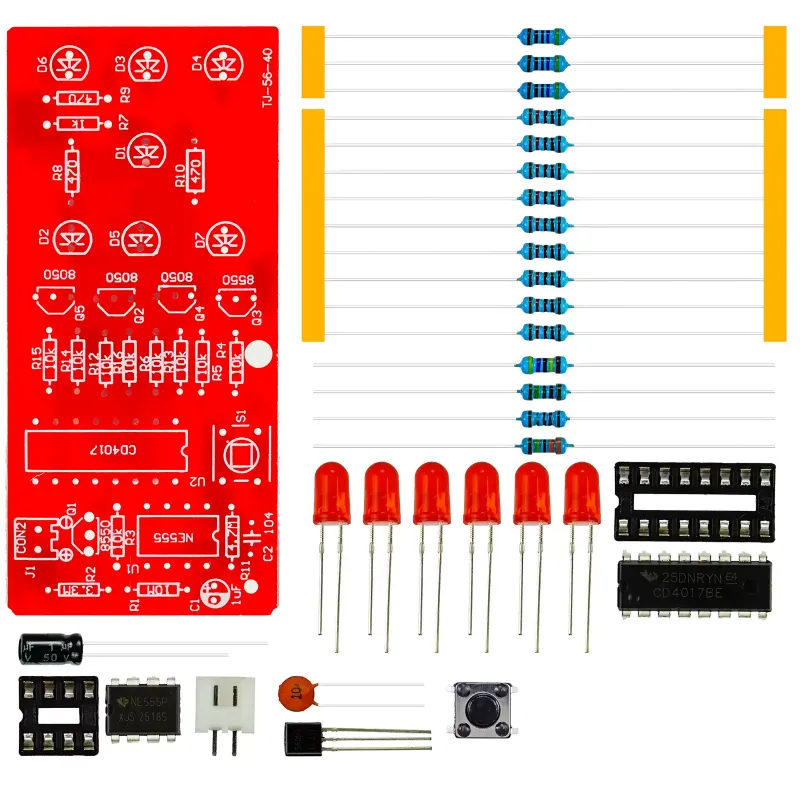
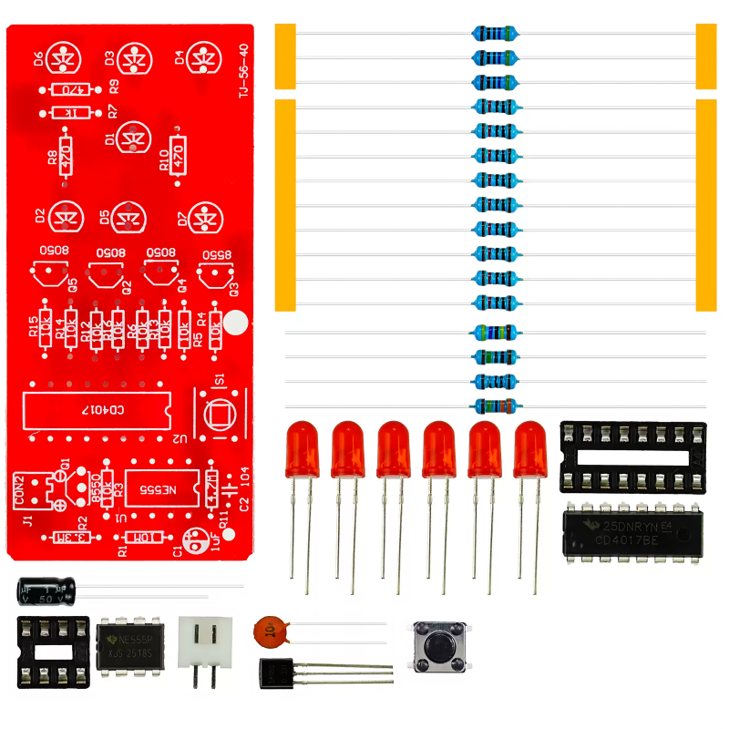
    Shipped as separate components
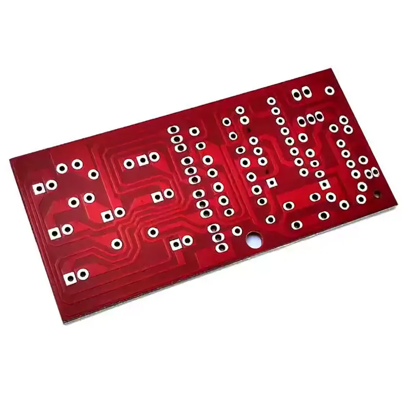
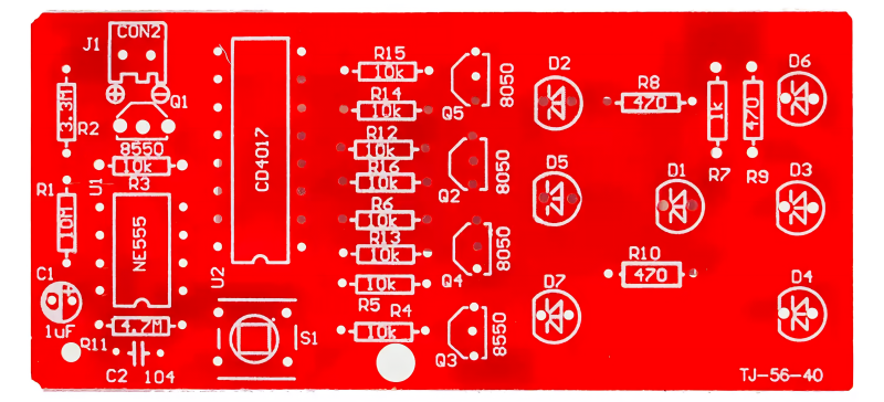
    High-quality circuit board

    Supplier Information

    Company:Robots gift store

    Email:[email protected]

    Tel:13273966089

    Recommended products

    4-in-1 Solar-Powered Space Fleet Model Kit for Kids, STEM Science Toy

    4-in-1 Solar-Powered Space Fleet Kit lets children build space-themed models while exploring solar energy, mechanics, and engineering through hands-on STEM activities.

    collect:0

    13-in-1 DIY Solar Robot Kit for Kids, Educational STEM Assembly Toy

    13-in-1 DIY Solar Robot Kit lets children build multiple solar-powered models while exploring renewable energy, mechanics, and engineering through hands-on STEM learning.

    collect:0

    Programmable Remote Control T-Rex Dinosaur Toy with Lights & Sound - STEM Educational Engineering Gift for Kids

    Program sound, light & movement with this official RC T-Rex! A fun, interactive STEM engineering robot toy designed to boost kids' creativity & learning through play.

    collect:0

    DIY Mechanical Bionic Winged Dragon STEM Science Experiment Kit

    DIY Mechanical Bionic Winged Dragon Kit helps children explore mechanics, circuits, and engineering through hands-on assembly, encouraging creativity and STEM learning.

    collect:0