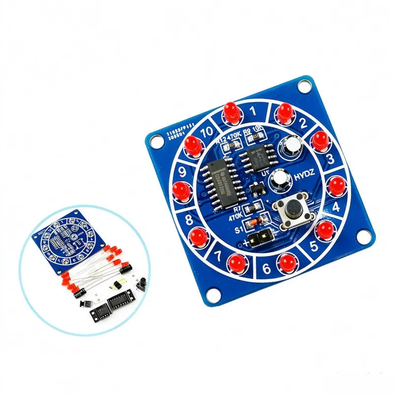


Product Description
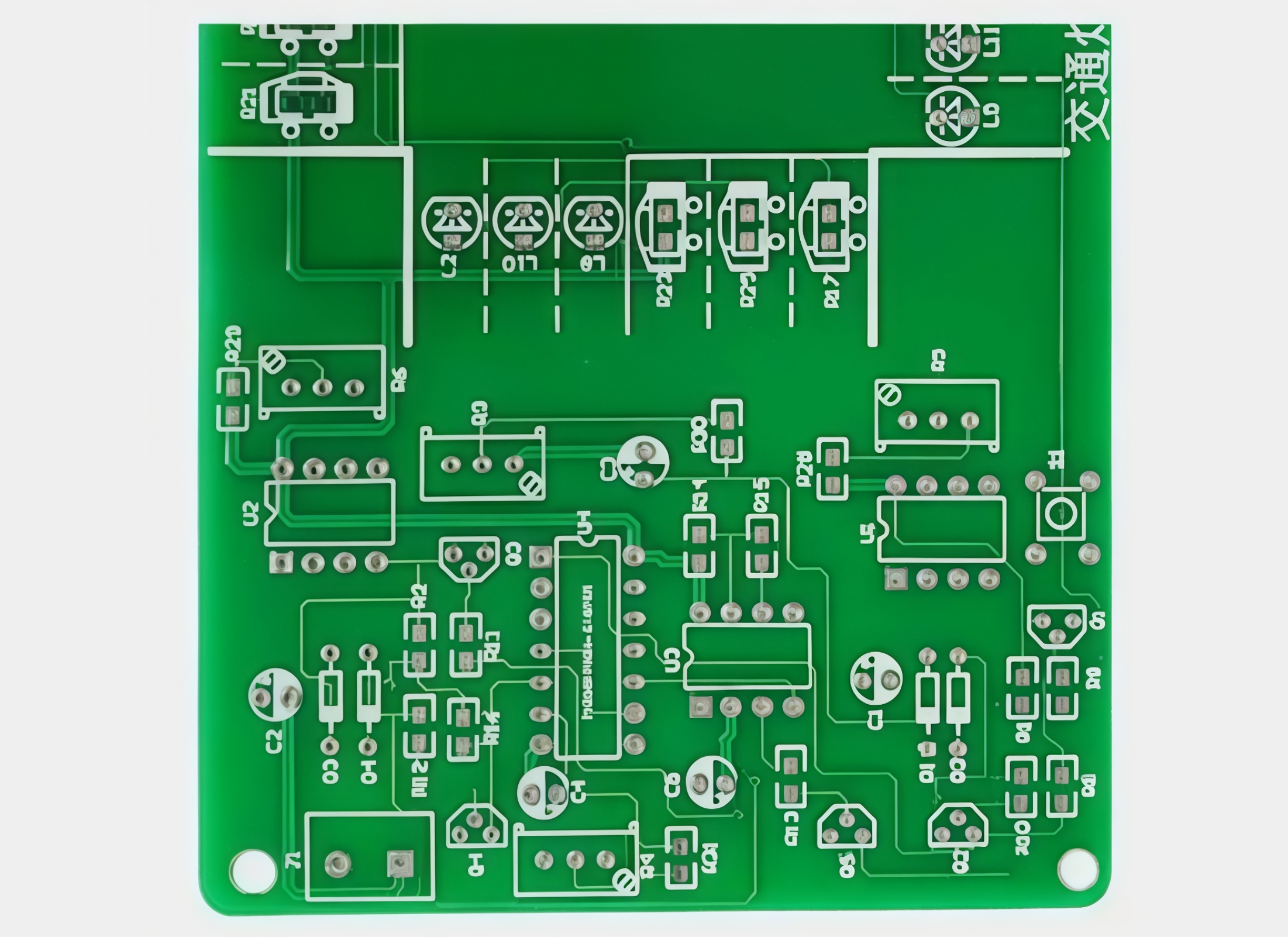
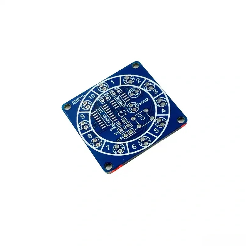
1. Made of KB-A grade FR-4 fiberglass board, 1.6mm thick; the board surface is flat and does not easily bend. Every PCB is flying-probe tested before leaving the factory, so the quality is dependable.
2. The circuit is already routed on the board and the pads are hot-air tin-sprayed, so the impedance is more stable and reliable, solder joints are easier to make and look nicer; pads also do not easily peel off after repeated soldering, which improves the fault tolerance and success rate of the experiment.
3. Component designators, parameters and orientation are printed directly on the PCB, so you can solder without consulting a circuit diagram; this shortens soldering time and reduces assembly errors, which is very convenient.
Functional Features
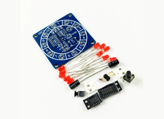
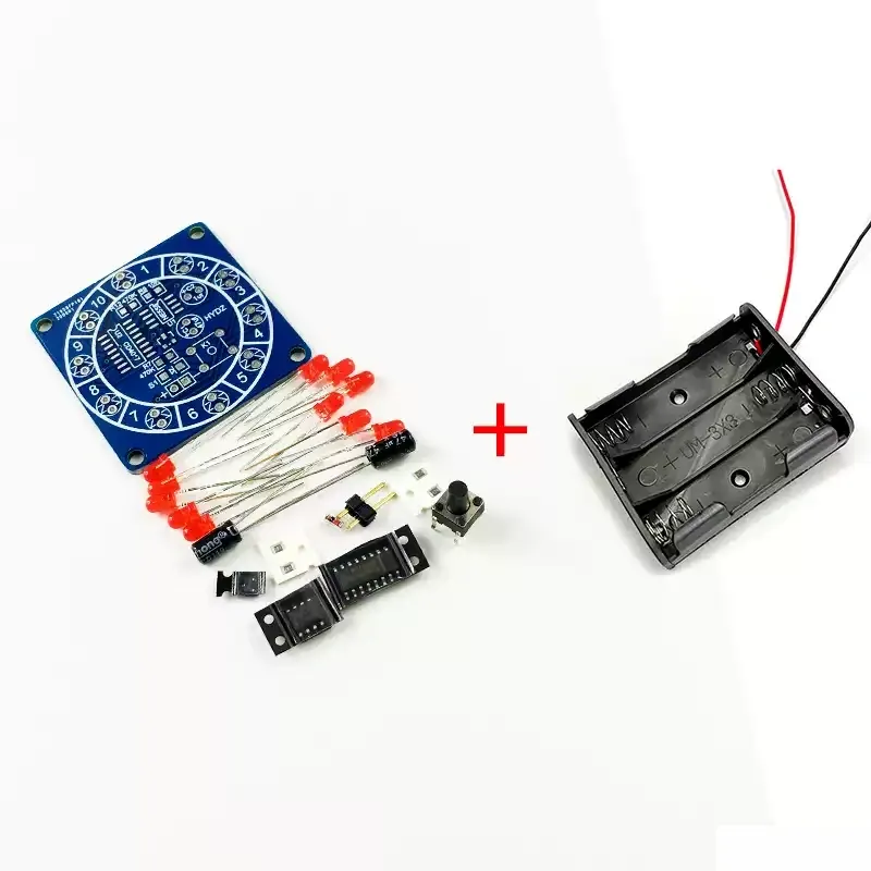
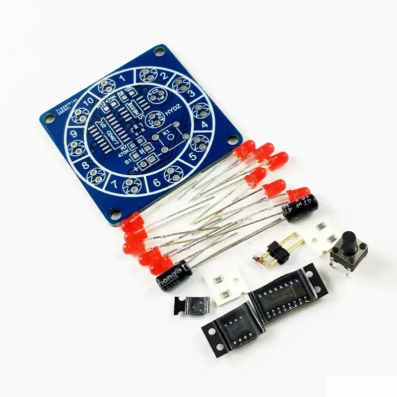
Loose parts as shipped
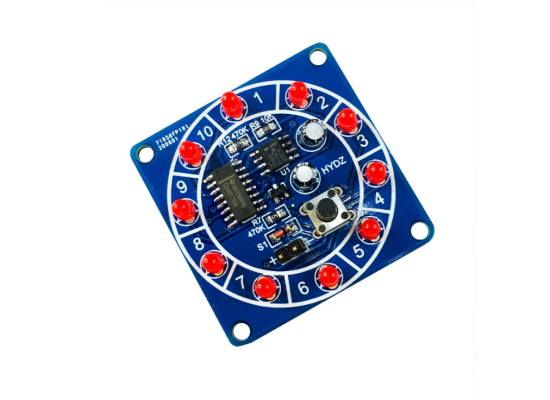
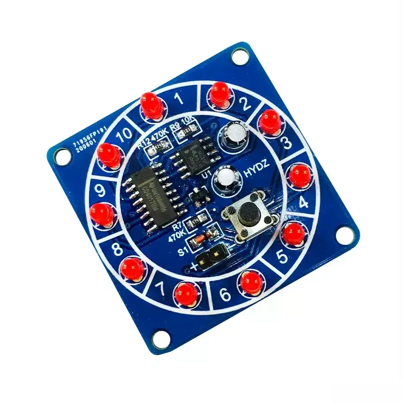
Assembled product after soldering
Notes:
Solder the components on the board starting from the smallest ones, then the larger ones.
If some components such as resistors and capacitors are temporarily out of stock, we will send components of the same symbol with nearby values; blue metal-film resistors may be replaced by gray carbon-film resistors, and gray carbon-film resistors may also be replaced by blue metal-film ones. The effect is the same.
After soldering, please debug it yourself; if there is no soldering error it will generally work. If soldering fails, we will do our best with after-sales service and help you complete the project.
Principles of Electric Circuits
| Circuit principle: the circuit mainly consists of a pulse generator and a decimal counter circuit. |
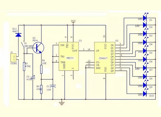
Circuit principle: the circuit mainly consists of a pulse generator and a decimal counter circuit.
The pulse generator consists of a multi harmonic oscillator composed of NE555 and peripheral components. When the button S1 is pressed, Q1 conducts, and the three pins of NE555 output pulses. The ten output terminals of CD4017 alternately output high levels to drive ten LEDs to emit light.
After releasing the button, due to the presence of capacitor C2, Q1 will not immediately turn off. As the voltage across C2 decreases, the conduction program of Q1 gradually weakens, and the frequency of the output pulse at pin 3 slows down, resulting in a slower LED movement frequency.
After the discharge of C2 is completed, Q1 is turned off, and pin 3 of NE555 no longer outputs pulses, causing the LED to stop moving. The lottery process was completed in this way. R2 determines the LED movement speed, and C2 determines the waiting time for the "lottery draw".
Product parameters
Parameter | Value |
Product Name | 12-face timer |
Kit Parameter | Value |
Supply Voltage | 3.5-6V |
Dimensions | 48*48MM |
Parts List
Component | Qty |
PCB board | 1 |
6*6*9 button | 1 |
1UF50V capacitor | 1 |
47UF25V capacitor | 1 |
3MM red LED | 10 |
1N4148 diode | 1 |
0805 470K resistor | 2 |
0805 10K resistor | 1 |
9014 transistor | 1 |
NE555 | 1 |