
Product Description
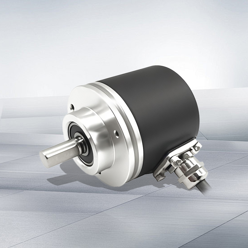
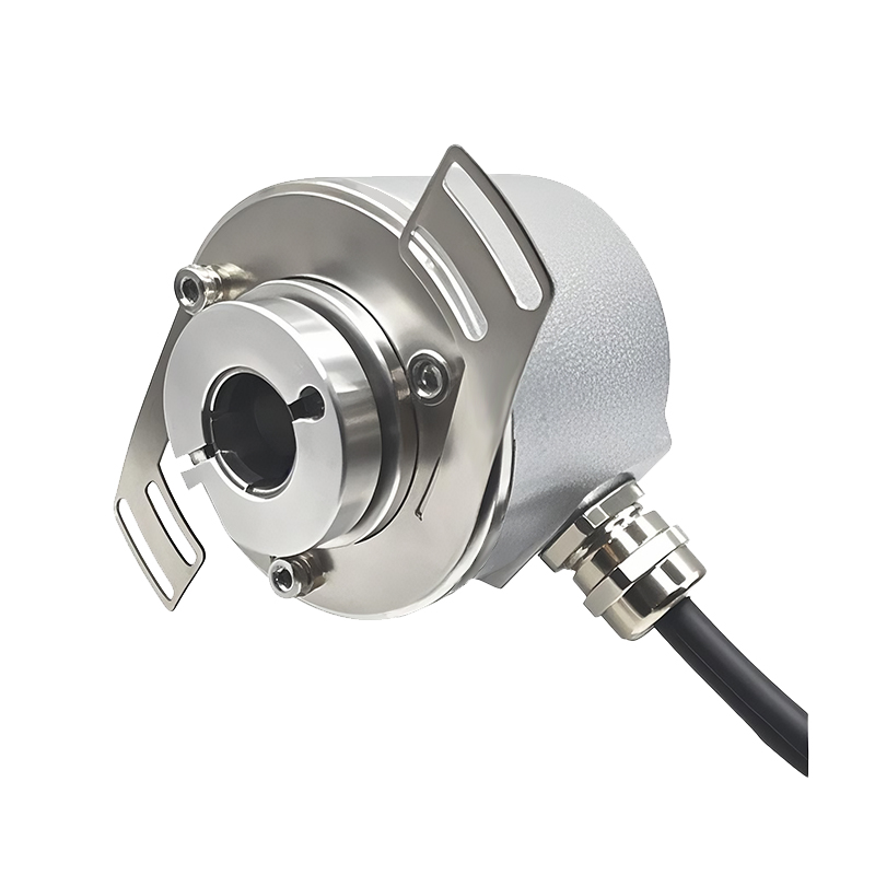
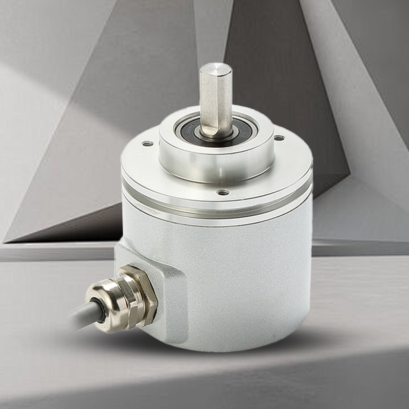
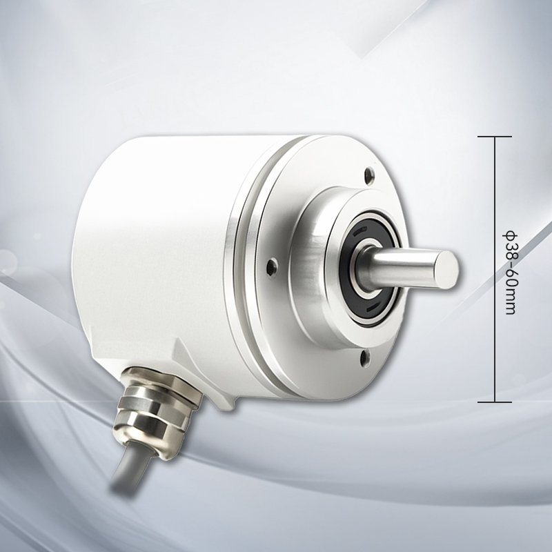
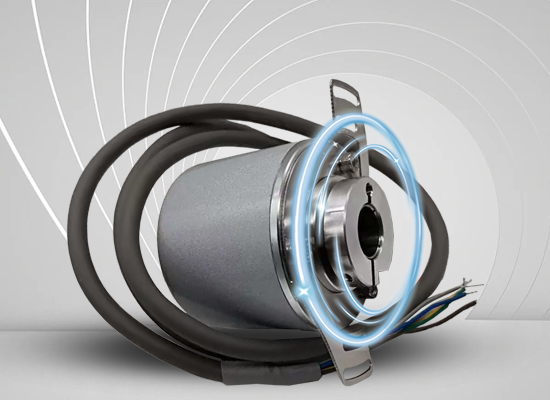
The absolute encoder RS485 series includes single-turn/multi-turn, 38/60mm specifications, supports RS485 protocol, has vibration resistance, wide temperature range and other characteristics, and is suitable for industrial automation scenarios.
Product parameters
Mechanical parameters | ||||
Single turn 38mm | Single turn 60mm | Multiple turns 38mm | Multiple turns 60mm | |
Maximum speed | 6000 rpm | |||
Spindle load | Axial 40N, radial 100N | |||
Impact resistance | 1000m/s²(6ms), equal to 100g | |||
Vibration resistance | 200m/s²(10-2000Hz), equal to 20g | |||
Axial movement allowed | ±1.5mm | |||
Radial runout allowed | ±0.2mm | |||
Appearance structure | 38mm outer diameter, solid shaft, blind hole shaft | 60mm outer diameter, solid shaft, blind hole shaft | 38mm outer diameter, solid shaft, blind hole shaft | 60mm outer diameter, solid shaft, blind hole shaft |
Connection type | 6-core shielded cable or aviation plug | |||
Electrical parameters | ||||
Single turn 38mm | Single turn 60mm | Multiple turns 38mm | Multiple turns 60mm | |
Working voltage | 10-30Vdc (5Vdc can be customized) | |||
Consumption current | < 50mA (24Vdc) no-load | |||
Output signal | RS485 free protocol | |||
Linear resolution | 1/4096FS~262144FS | |||
IP rating | IP65 (IP68 can be customized) | |||
Repeat positioning accuracy | Less than 2Bit | |||
Working cycles | 1 circle (360°) | 1 circle (360°) | 4096 circles | 4096 circles |
Working temperature: | -40℃~85℃ | |||
Storage temperature | -40℃~85℃ | |||
Wiring Diagram
Function | Vcc | GND | RS485 A | RS485 B | Set (optional) | Set to allow | Block |
Color | Brown | White | Green | Yellow | Gray | Blue | Net (thick red) |
Note: 1. Use of setting permission line (blue)
In setting mode: the blue line and brown line of the encoder are connected together to the positive power supply. At this time, the communication rate of the encoder is fixed at 19200bps.
Non-setting mode: that is, when working normally, it is recommended to connect the blue line and white line together to the power ground line.
2. Use of set line (gray)
When the set line (gray) touches Vcc for more than 1 second, the current data of the encoder becomes the set value (the set value of the encoder can be set arbitrarily)
The encoder can also be set using instructions (see Example 3 for specific instructions)
Mechanical Dimensions
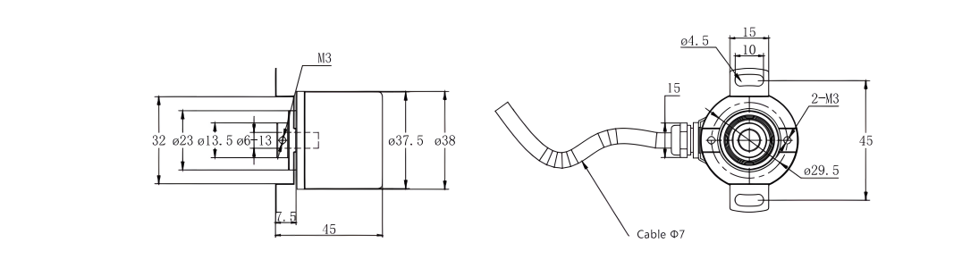
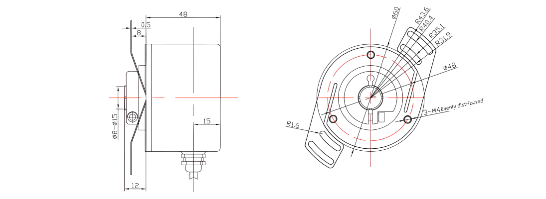
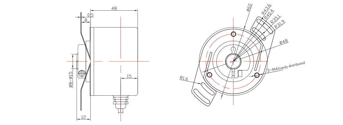
Single turn 38mm
Clamping flange (cable output or plug output optional)
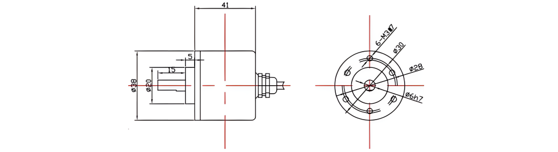
38mm outer diameter 6mm shaft diameter optional 15mm shaft length Radial outlet optional
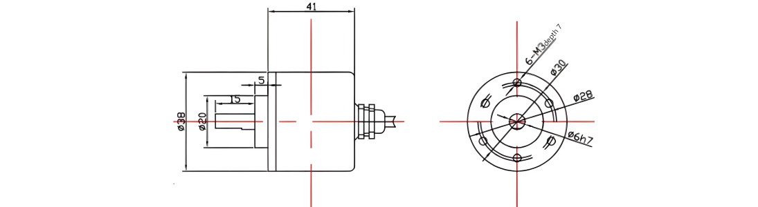
Synchronous flange / servo flange (cable output or plug output optional)
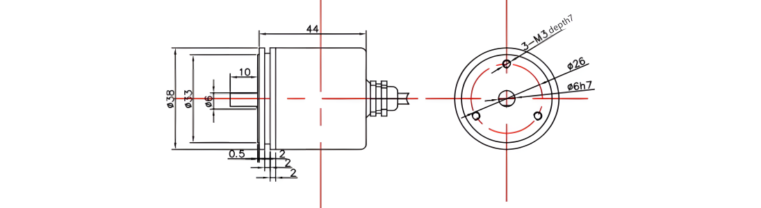
38mm outer diameter 6mm shaft diameter 10mm shaft length Radial outlet optional
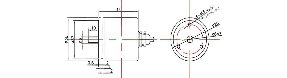
Blind hole type / semi-through hole flange (cable output or plug output optional)
38mm outer diameter 6/8mm hole diameter optional 13mm hole depth Axial outlet optional
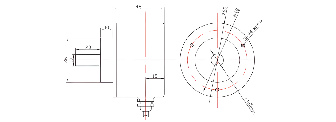
Single turn 60mm
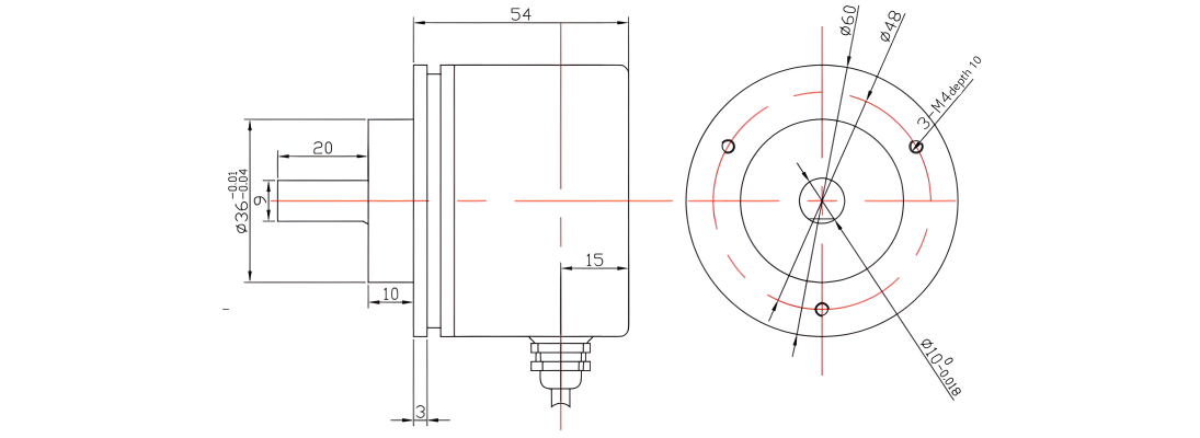
Clamping synchronous flange (cable output or plug output optional)
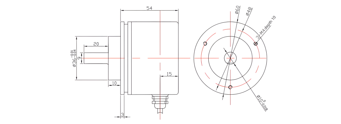
60mm outer diameter 6/8/10mm shaft diameter optional 20mm shaft length Axial outlet optional
Clamping flange (cable output or plug output optional)
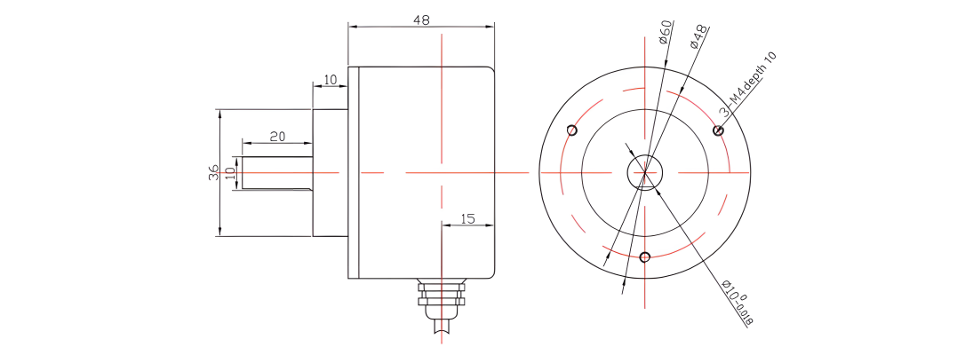
60mm outer diameter 6/8/10mm shaft diameter optional 20mm shaft length Axial outlet optional
Synchronous flange / servo flange (cable output or plug output optional)
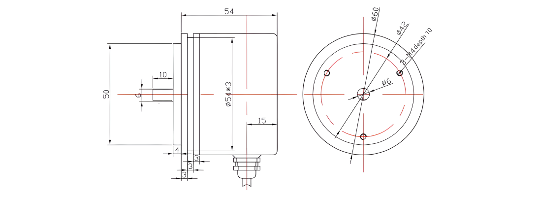
60mm outer diameter 6mm shaft diameter 10mm shaft length Axial outlet optional
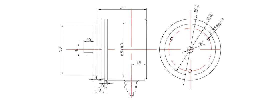
Blind hole type / semi-through hole flange (cable output or plug output optional)
60mm outer diameter 8-15mm hole diameter optional 20mm hole depth Axial outlet optional
Multiple turns 38mm
Clamping flange (cable output or plug output optional)
38mm outer diameter 6mm shaft diameter optional 15mm shaft length Radial outlet optiona
Synchronous flange / servo flange (cable output or plug output optional)
38mm outer diameter 6mm shaft diameter 10mm shaft length Radial outlet optional
Blind hole type / semi-through hole flange (cable output or plug output optional)

38mm outer diameter 6/8mm hole diameter optional 13mm hole depth Axial outlet optional
Multiple turns 60mm
Clamping synchronous flange (cable output or plug output optional)
60mm outer diameter 6/8/10mm shaft diameter optional 20mm shaft length Axial outlet optional
Clamping flange (cable output or plug output optional)
60mm outer diameter 6/8/10mm shaft diameter optional 20mm shaft length Axial outlet optional
Synchronous flange / servo flange (cable output or plug output optional)
60mm outer diameter 6mm shaft diameter 10mm shaft length Axial outlet optional
Blind hole type / semi-through hole flange (cable output or plug output optional)
60mm outer diameter 8-15mm hole diameter optional 20mm hole depth Axial outlet optional
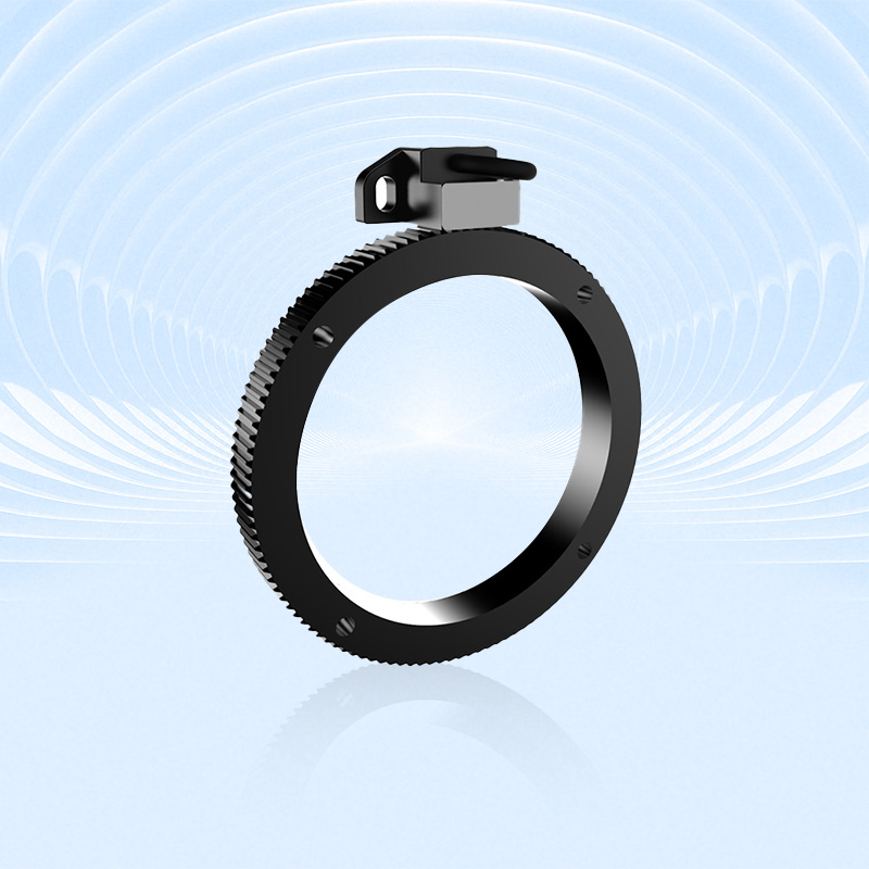
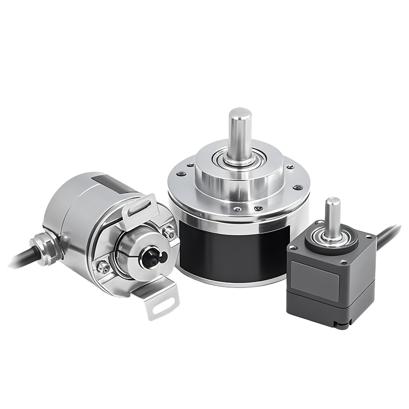
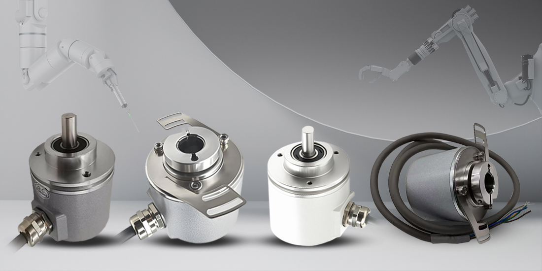
Product Display
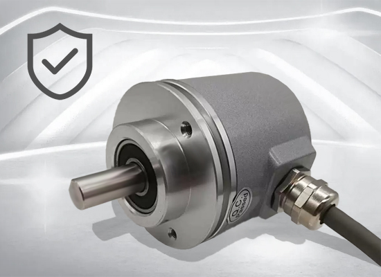
Multiple specifications available: 38/60mm outer diameter, single-turn/multi-turn type, suitable for different installation scenarios
High protection level: IP65 protection (IP68 customizable), adaptable to harsh industrial environments
Wide temperature operation: -40℃~85℃ wide temperature range, strong resistance to high and low temperatures
Shock and vibration resistance: shock resistance 1000m/s², vibration resistance 200m/s², good mechanical stability
High-precision feedback: repeated positioning accuracy <2Bit, linear resolution 1/4096FS~262144FS
Flexible communication: RS485 free protocol, baud rate 4800-115200bps adjustable, support active and passive mode
Dual setting function: hardware setting line and command setting dual mode, real-time calibration position
Maintenance-free design: multi-turn type has 4096 working turns, power-off memory position
Anti-interference ability: double-shielded cable, power isolation design, adapt to strong electromagnetic environment
Easy installation: a variety of flange structures (clamping/synchronous flange), solid/blind hole shaft optional
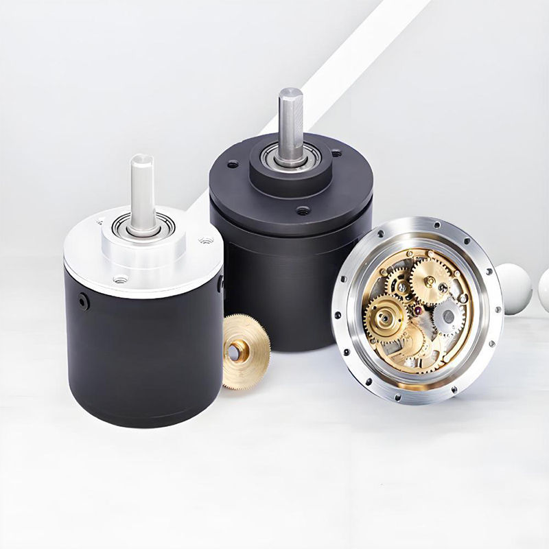
Quality Control
The quality of encoders is directly related to the stability and reliability of industrial automation systems. We have built a full-process quality control system, strictly screening suppliers from raw material procurement to ensure that the performance of core components meets standards; in the production process, we use high-precision equipment and standardized processes, and cooperate with online detection technology for real-time monitoring; in the finished product stage, we conduct rigorous tests such as high and low temperature, electromagnetic compatibility, and life aging to eliminate performance risks. Each encoder has passed multiple quality inspection levels, and its excellent quality has laid a solid foundation for intelligent manufacturing, providing customers with long-term and stable use guarantees.

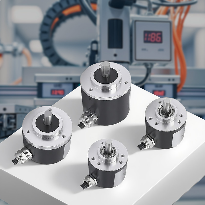
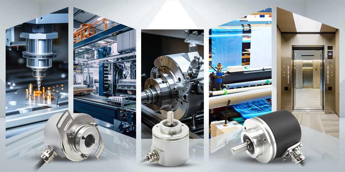
Application Cases
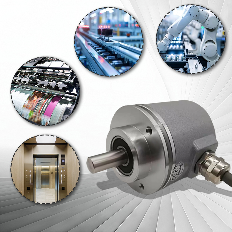
It is suitable for industrial automation scenarios such as machine tool spindle positioning, packaging machinery station calibration, collaborative robot joint angle detection, wind power pitch control, solar tracking and other new energy equipment, elevator car positioning, crane arm monitoring, metallurgical and chemical harsh environments and compact machinery, blind hole shaft equipment installation.
Communication protocol description
Baud rate: 4800bps, 9600bps, 19200bps, 38400bps, 115200bps.
Frame format: 8 data bits, 1 stop bit, no parity check, no control flow.
The encoder parameters need to be set by software instructions.
When the encoder is in active mode, the encoder actively sends data to the host computer. The data length is 16-bit hexadecimal ASCII code, the format is: XAB>±DATA↙, that is:
1 | 2 | 3 | 4 | 5 | 6 | 7 | 8 | 9 | 10 | 11 | 12 | 13 | 14 | 15 | 16 | ||
X | Address | > | ± | DATA | ↙ | ||||||||||||
Among them, "X" is the leading letter, > is the separator, and ± is the sign bit. DATA is the data, in ASCII format, 10 bits, consisting of 0 to 9, ranging from -9,999,999,999 to +9,999,999,999. The last is the carriage return character (0D).
When the encoder address is in passive mode, that is, question-and-answer mode. The host computer sends an inquiry command to the encoder. The command is a 4-bit hexadecimal ASCII code in the format of: D+AB↙.
AB is the encoder address, ranging from 0 to 99
Routine
1: Read data:
The host computer sends: D+address+0D Encoder returns: X+address+>+match bit+data bit+0D
Example: The host computer sends 44 30 31 0D (when the encoder address is 01)
Encoder returns: 58 30 31 3E 2B 30 30 30 30 30 30 30 31 32 33 0D
2: Encoder set command:
The host computer sends: D+address+L+ M+sum check+0D Encoder returns: X+address+l+ m+sum check+0D
Example: The host computer sends: 44 30 31 4C 4D sum check 0D (when the encoder address is 01)
Encoder returns: 58 30 31 6C 4D sum check 0D (set current position)
Please use our company's special ZHCOD software and usage instructions for encoder parameter setting: please call our company to obtain (see the figure below)
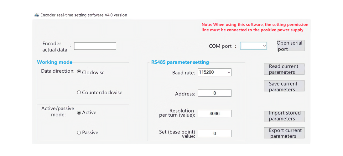 Software Instructions:
1. Data direction
Clockwise is the positive direction: facing the encoder shaft, the encoder data increases when rotating clockwise
Counterclockwise is the positive direction: facing the encoder shaft, the encoder data increases when rotating counterclockwise
2. Set the active/passive mode:
Active mode is broadcast mode
Passive mode is question-and-answer mode
3. Set the baud rate when the RS485 signal is working:
Setting range: 4800-115200
4. Set the resolution per turn: that is, the data output by the encoder when the encoder rotates one turn
Any setting within 1-4096
5. Set the encoder RS485 signal address:
Setting range: 0--99
6. Set the set value:
1. When the set line (gray) touches the positive pole of the power supply for more than 1 second, the current value of the encoder becomes the set set value.
2. When the set command is sent to the encoder, the current value of the encoder becomes the set set value. (Example 2)
Read current parameters:
Read the current parameters of the encoder before setting
Save current parameters:
Write the parameters required to be modified in the encoder
Export current parameters:
Save the saved current parameters to a specified place on the computer.
So that you can directly import the stored parameters when you use them again in the future.
Import stored parameters:
Import the previously exported current parameters into the software and use them.
Notes on RS485 communication:
1. Communication rate and transmission distance are contradictory. The higher the rate, the closer the transmission distance, but also the more stable, and vice versa.
2. When the external electromagnetic interference is strong, the external set line needs to be connected to a high level when setting the encoder, but it is recommended to force a low level after the setting is completed to prevent the encoder from suddenly returning to zero due to external interference.
3. When the external electromagnetic interference is strong, it is best to use a double-shielded cable for RS485 wiring.
4. When multiple encoders are connected to the host computer, since the encoder return data has no parity check, it is recommended to distinguish the data returned by each encoder in time when programming the host computer.
5. When there is a motor in the system, the encoder power supply needs to be isolated from other power supplies.
Since the RS485 circuit is differential, A+ and B- are both voltage-carrying, and often grounding or connecting to a high level will cause damage to the RS485 circuit.