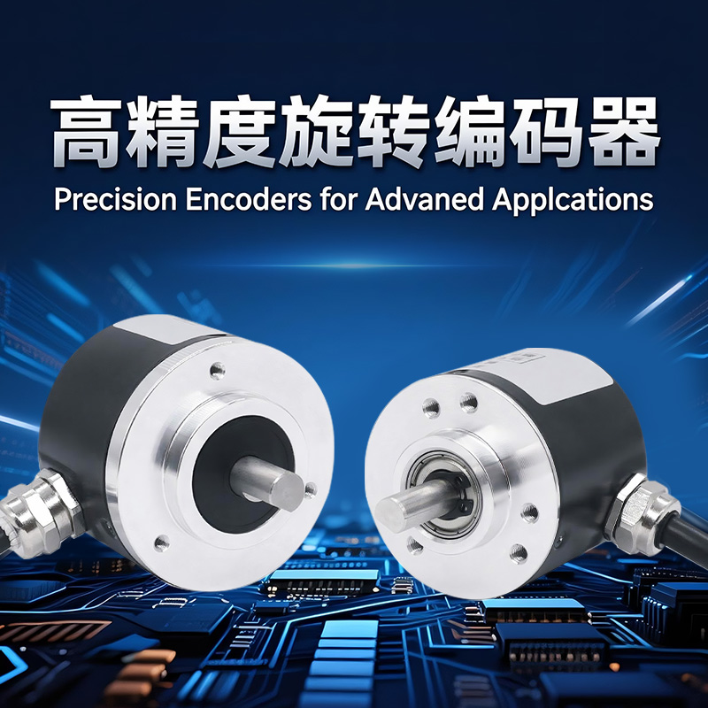

Product Description
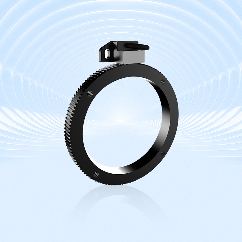
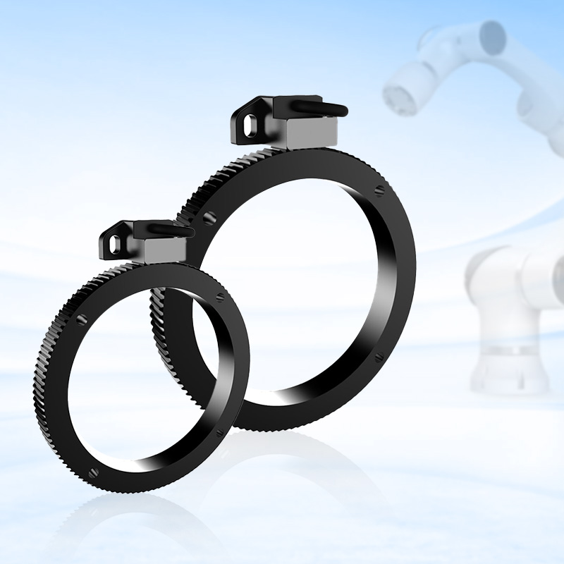
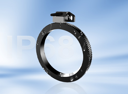
The EWH38H series is a bearingless incremental magnetic encoder featuring IP68 protection, a high speed of 30,000 RPM, and a resolution of 4096 PPR. It is compatible with a wide range of gears and shaft diameters for precise motion control.
Product parameters
Shaft Diameter | Φ15mm-Φ290mm optional (1) |
Probe Sensing Distance | 0.15mm±0.02mm |
Gear Module Range | 0.4, 0.5mm |
Number of Gear Teeth | 128, 256, 512, 1024 optional (1) |
Maximum RPM | 30000RPM |
Protection Rating | IP68 |
Operating Temperature | -20℃~+80℃ |
Storage Temperature | -40℃~+85℃ |
Weight | ≈0.7Kg |
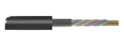
Wire Output | Cable length 0.5m |
Note: (1) Refer to the gear specification table.
Electrical Specifications
Output Circuit | RS422 (TTL compatible) |
Power Supply Voltage | DC5V±10% |
No-Load Current Consumption | Maximum 80 mA |
Maximum Load Current | ±50 mA |
Maximum Output Frequency | 500 kHz |
Signal High Level | Minimum 2.5V |
Signal Low Level | Maximum 0.4V |
Rise Time Tr | Maximum 1μs |
Fall Time Tf | Maximum 1μs |
Short Circuit Protection | Yes |
Terminal Configuration
Signal |
| OV | +Ub | A | `A | B | `B | O | `O |
Color Code |
| White | Brown | Green | Yellow | Blue | Red | Gray | Pink |
WH | BN | GN | YE | BU | RD | GY | PK |
Gear Specifications
Module 0.4mm
Type | Outer Diameter DX (mm) | Inner Diameter ID (mm) | PCD/Dh (mm) | Mounting Hole Ha (mm) | Number of Teeth | Remarks |
C04-1024.A01 | 410.4 | 290 | None | None | 1024 | Keyway |
C04-512.A01 | 205.6 | 180 | 194.4 | 4.5 | 512 | 4 φ4.5 mounting holes |
C04-512.A01 /1 | 205.6 | 180 | 194.4 | 4.5 | 512 | 4 φ4.5 mounting holes, 2 M4 tapped holes |
C04-512.A02 | 205.6 | 180 | 175 | 4.5 | 512 | 4 φ4.5 mounting holes, 2 M4 tapped holes |
C04-512.A03 | 205.6 | 160 | 175 | 4.5 | 512 | 4 φ4.5 mounting holes |
C04-512.A04 | 205.6 | 140 | 175 | 4.5 | 512 | 4 φ4.5 mounting holes, 2 M4 tapped holes |
C04-512.A05 | 205.6 | 108 | 124 | 5.5 | 512 | 6 φ5.5 mounting holes, 2 M4 tapped holes |
C04-512.A06 | 205.6 | 130 | 155 | 4.5 | 512 | 4 φ4.5 mounting holes, 2 M4 tapped holes |
C04-512.A07 | 205.6 | 150 | 180 | 6.5 | 512 | 6 φ6.5 mounting holes, 2 M4 tapped holes |
C04-384.A01 | 154.4 | 108 | 120 | 4.5 | 384 | 4 φ4.5 mounting holes, 2 M4 tapped holes |
C04-384.A02 | 154.4 | 108 | 124 | 5.5 | 384 | 6 φ5.5 mounting holes |
C04-384.A03 | 154.4 | 130 | 143 | 5.5 | 384 | 4 φ5.5 mounting holes |
C04-384.A03 /1 | 154.4 | 130 | 142 | 4.5 | 384 | 6 φ4.5 mounting hole countersunk holes |
C04-256.A01 | 103.2 | 82 | 92 | 4.5 | 256 | 4 φ4.5 mounting holes |
C04-256.A01 /1 | 103.2 | 82 | 92 | 4.5 | 256 | 4 φ4.5 mounting holes, 2 M3 tapped holes |
C04-256.A02 | 103.2 | 90 | 96 | 3.5 | 256 | 2 φ3.5 mounting holes |
C04-256.A02 /1 | 103.2 | 90 | 96 | 3.5 | 256 | 6 φ3.6 mounting holes |
C04-256.A03 | 103.2 | 65 | 80 | 9 | 256 | 6 φ7 countersunk holes, 3 M6 tapped holes |
C04-256.A04 | 103.2 | 45 | 无 | 无 | 256 | No mounting holes, no keyway |
C04-256.A05 | 103.2 | 60 | 80 | 4.5 | 256 | 4 φ4.5 mounting holes |
C04-256.A06 | 103.2 | 75 | 90 | 4.5 | 256 | 4 φ4.5 mounting holes |
C04-256.A07 | 103.2 | 90 | 96.8 | M4 | 256 | 4 M4 tapped holes, 1/3 broken tooth special |
C04-200.A01 | 80.8 | 60 | 70 | 3.5 | 200 | 4 φ3.5 mounting holes |
C04-192.A01 | 77.6 | 52 | 65 | 3.5 | 192 | 4 φ4.5 mounting holes |
C04-128.A01 | 52 | 35 | 43 | 3.5 | 128 | 4 mounting holes with countersunk holes |
C04-128.A01 /1 | 52 | 35 | 43 | 3.5 | 128 | 4 mounting holes with reverse countersunk holes |
C04-128.A02 | 52 | 30 | 41 | 3.5 | 128 | 4 mounting holes with countersunk holes |
C04-128.A03 | 52 | 35 | 43 | 3.5 | 128 | 6 mounting holes with custom threading |
C04-128.A04 | 52 | 25 | 39 | 3.5 | 128 | 4 mounting holes with countersunk holes |
C04-128.A05 | 52 | 15 | 30 | M5 | 128 | 2 MS tapped holes |
C04-100.A01 | 40.8 | 20 | 30 | 3.5 | 100 | 4 mounting holes without countersunk holes |
C04-100.A02 | 40.8 | 25 | None | None | 100 | - |
C04-64.A01 | 26.4 | 10 | None | None | 64 | - |
Module 0.5mm
Type | Outer Diameter DX (mm) | Inner Diameter ID (mm) | PCD/Dh (mm) | Mounting Hole Ha (mm) | Number of Teeth | Remarks |
C05-512.A01 | 257 | 230 | 244 | 4.5 | 512 | 4 φ4.5 mounting holes, 2 M4 tapped holes |
C05-512.A02 | 257 | 235 | 244 | 4.5 | 512 | 4 φ4.5 mounting holes, 2 M4 tapped holes |
C05-512.A03 | 257 | 200 | 244 | 4.5 | 512 | 4 φ4.5 mounting holes, 2 M4 tapped holes |
C05-384.A01 | 193 | 160 | 175 | 7 | 384 | 4 φ7 mounting holes, 2 M6 tapped holes |
C05-256.A01 | 129 | 95 | 112 | 3.5 | 256 | 4 φ4.5 mounting holes, 2 M4 tapped holes |
C05-128.A01 | 65 | 50 | 57 | 3.5 | 128 | 4 φ3.5 mounting holes |
C05-128.A02 | 65 | 40 | 53 | 4.5 | 128 | 4 φ4.5 mounting holes |
C05-128.A03 | 65 | 48 | 55 | 3.5 | 128 | 4 φ3.5 mounting hole countersunk holes |
C05-128.A04 | 65 | 38 | 48 | 4.5 | 128 | 4 φ8/4.5 mounting holes, countersunk holes |
C05-128.A05 | 65 | 40 | 52 | 4.5 | 128 | 4 φ8/4.5 countersunk holes, 4 φ4.5 through holes |
C05-128.A06 | 65 | 33.3 | 53 | - | 128 | 4 φ4.5 mounting holes, 2 M5 through holes, 18 M4 deep 7" holes |
C05-64.A01 | 33 | 15 | None | None | 64 | None |
Note: Bold indicates commonly used specifications.
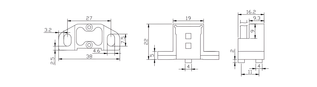
Mechanical Dimensions
EWH38H Series
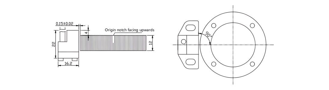
EWH38H Series Probe Hole Locations
Selection Guide
EWH38 | H | 25 | - | E | 512 | L | - | 5 | 04 | T | 04 | R | 0.5 | / | XXXX | |||||||||
↑ | ↑ | ↑ | ↑ | ↑ | ↑ | ↑ | ↑ | ↑ | ↑ | ↑ | ↑ | |||||||||||||
① | ② | ③ | ④ | ⑤ | ⑥ | ⑦ | ⑧ | ⑨ | ⑩ | ⑪ | ⑫ |
① Spindle type H: Hollow shaft | ② Shaft diameter (1) Module 0.4mm gear: 25(Φ25), 35(Φ35), 82(Φ82), 180(Φ180), 290(290) | Module 0.5mm gear: 50(Φ50), 95(Φ95) | ③ Output channel E: A, -A, B, -B,O, -O | ④ Resolution
128, 256, 512, 1024, 2048, 4096 | ⑤ Output type
L: RS422 (TTL compatible)
| ⑥ Power supply voltage
5: 5V |
⑦ Gear module
04: Module 0.4mm gear 05: Module 0.5mm gear | ⑧ Output Waveform
T: Square Wave | ⑨ Frequency Odds
02: 2-fold frequency 04: 4-fold frequency 08: 8-fold frequency 16: 16-foldfrequency | ⑩ Cable Outlet
R: Cable Radius | ⑪ Connection Method
Digit: Cable Length (Unit: m) | ⑫ Special Code | |
Note: (1) For other specifications, refer to the gear specification table
Installation Notes:
The gear must be aligned with the center of the reader head. Ensure that the gear runout and concentricity are ≤0.02mm.
The distance between the top of the reader head and the gear plate must be 4mm.
The clearance between the reader head and the gear must be 0.15±0.02mm. Avoid touching the reader head to avoid damage.
The gear must be protected from damage.
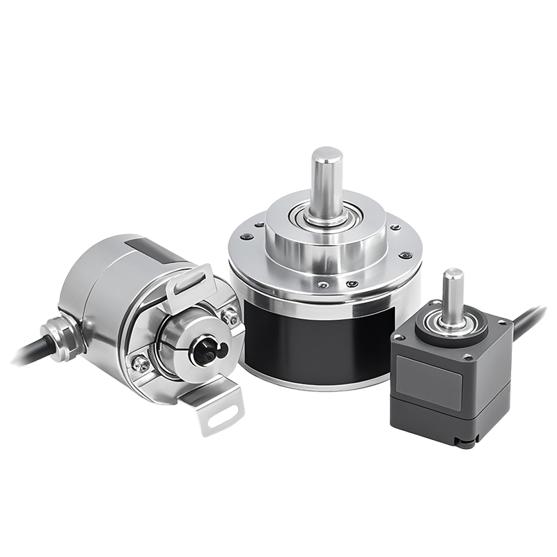
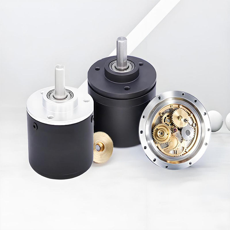
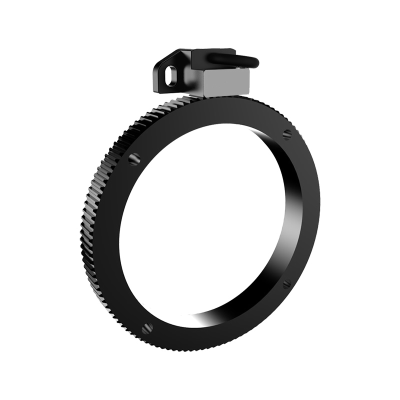
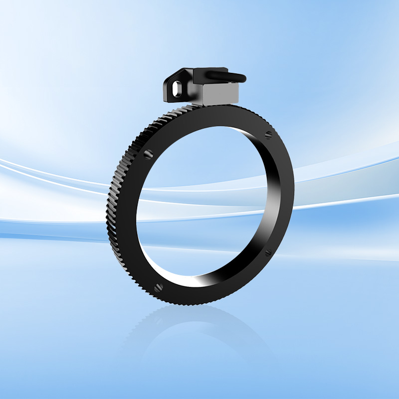
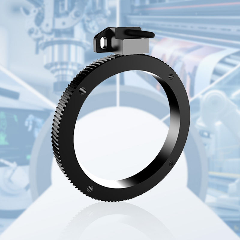
Product Display
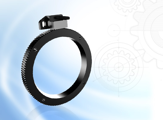
Bearingless design reduces wear and improves durability.
Magnetic sensing provides stable signals and adapts to complex operating conditions.
IP68 protection resists dust and moisture, making it suitable for harsh environments.
Up to 4096PPR resolution provides accurate feedback and is suitable for precision control.
Supports high speeds of 30,000 RPM, making it suitable for high-speed applications.
RS422 output with short-circuit protection ensures electrical stability and reliability.
Quality Control
The quality of encoders is directly related to the stability and reliability of industrial automation systems. We have built a full-process quality control system, strictly screening suppliers from raw material procurement to ensure that the performance of core components meets standards; in the production process, we use high-precision equipment and standardized processes, and cooperate with online detection technology for real-time monitoring; in the finished product stage, we conduct rigorous tests such as high and low temperature, electromagnetic compatibility, and life aging to eliminate performance risks. Each encoder has passed multiple quality inspection levels, and its excellent quality has laid a solid foundation for intelligent manufacturing, providing customers with long-term and stable use guarantees.

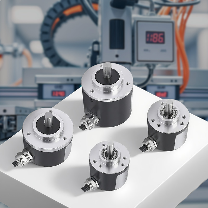
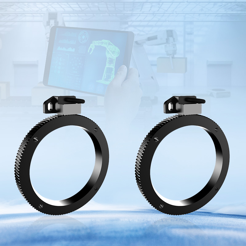
Application Cases
This series of bearingless incremental encoders is suitable for motion control applications requiring precise position and velocity feedback, such as industrial automation, robotics, and new energy equipment.