
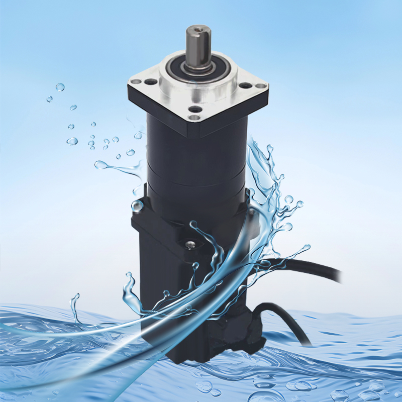
Product Description
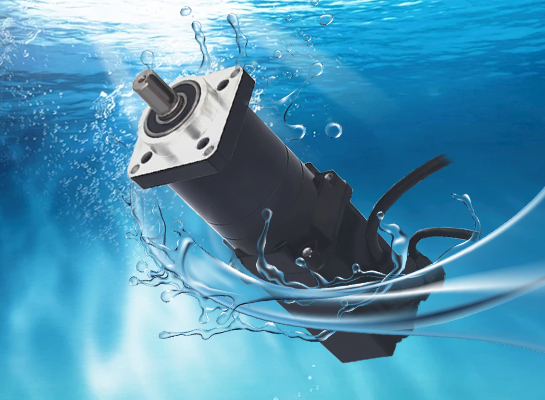
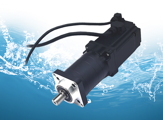
【IP68 fully sealed Protection 】 Submersible planetary gear motor | Triple protection against corrosion, rust and dust
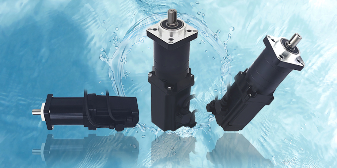
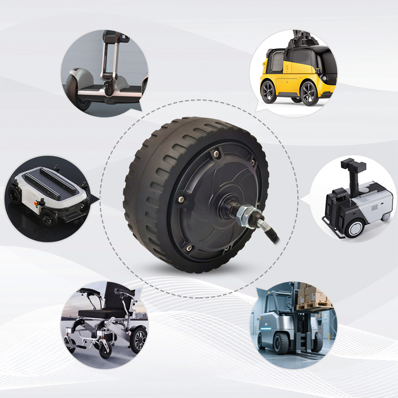
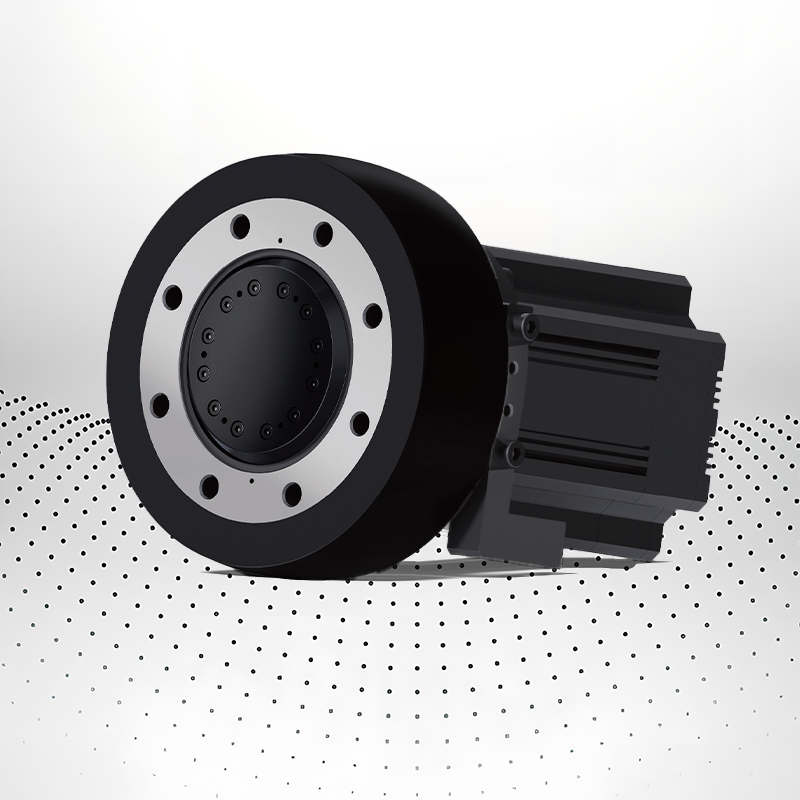
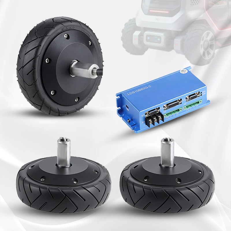
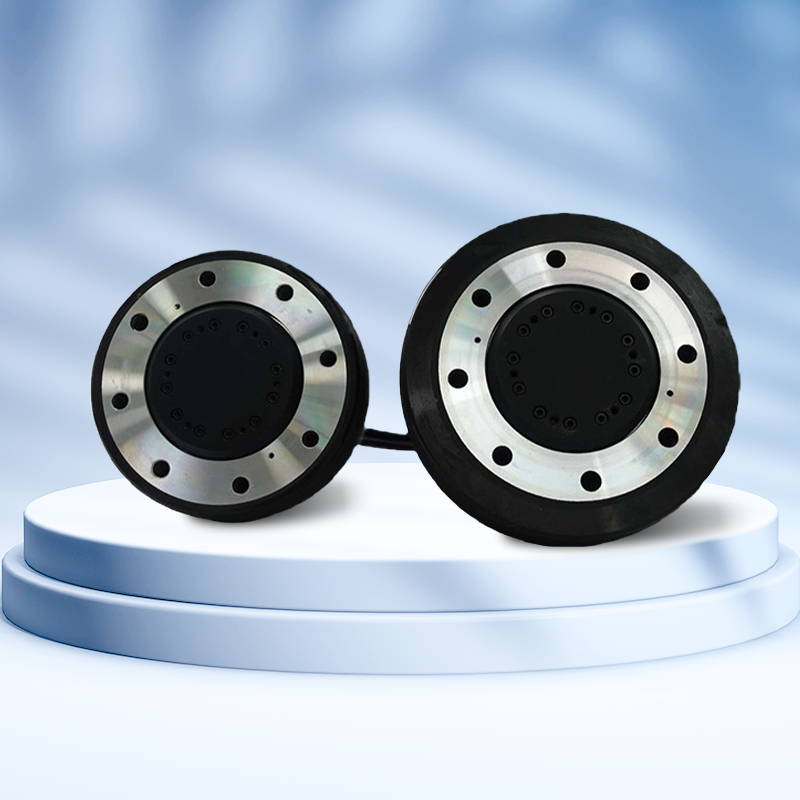
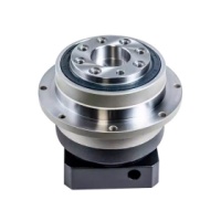
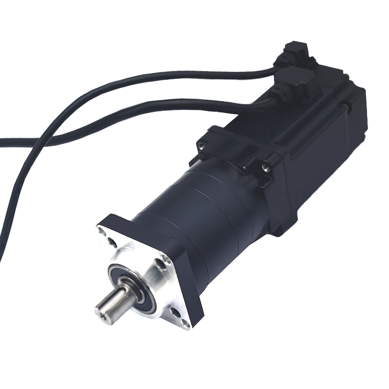
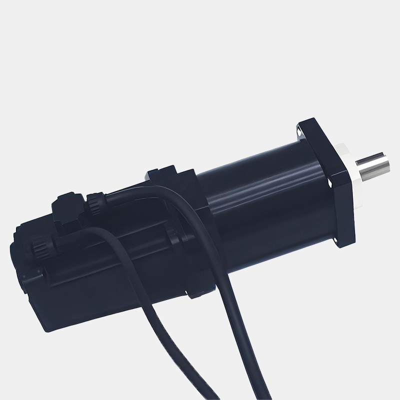
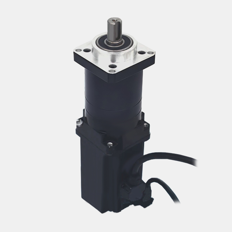
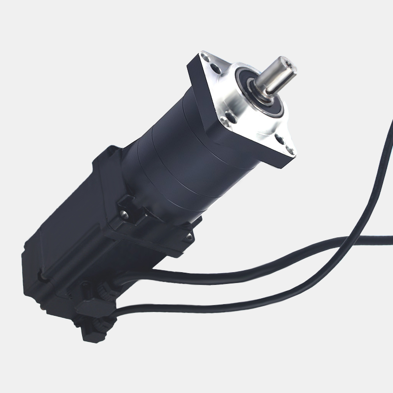
Product Display
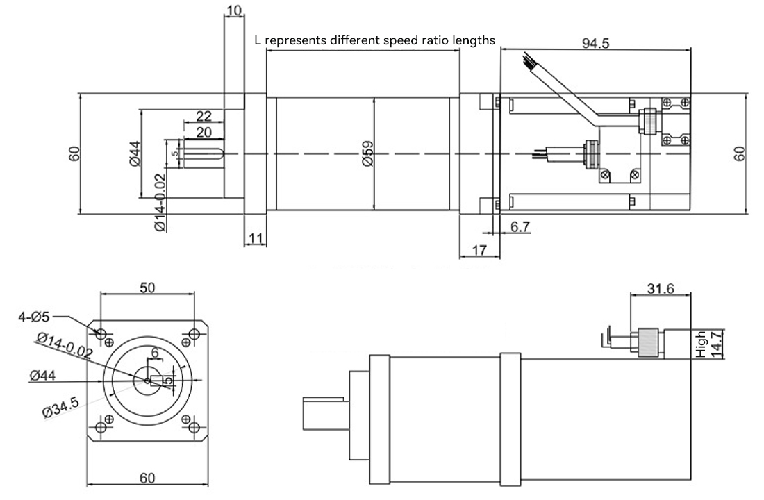
Dimensional drawing
Product parameters
Parameter table of Micro DC motor | |||
Name | Parameters | Name | Parameters |
Model | BL60-94FS | Rotational speed range | 7-50ORPM |
Voltage range | 12V-24V | Rated current | 15A |
Power | 500W | Whether to adjust the speed | 是 |
BL60-94 Planetary waterproof motor | ||||||||||
Reduct ion ratio | No-Load | Rated Load | Stal1 | Weight | ||||||
Rated | Speed | CURRENT | Speed | CURRENT | Torque | Power (w) | Torque | CURRENT | ||
3 | 24V | 500 | 1.5 | 420 | 6.5 | 5 | 250/500 | 15 | 15 | 2.3 |
5 | 24V | 300 | 1.5 | 260 | 6.5 | 7 | 250/500 | 20 | 15 | 2.3 |
10 | 24V | 150 | 1.5 | 120 | 6.5 | 13 | 250/500 | 28 | 15 | 2.3 |
20 | 24V | 75 | 1.5 | 60 | 7 | 35 | 250/500 | 45 | 15 | 2.3 |
28 | 24V | 50 | 1.6 | 40 | 7 | 43 | 250/500 | 55 | 20 | 2.5 |
35 | 24V | 40 | 1.6 | 30 | 7 | 50 | 250/500 | No blocking or turning | 20 | 2.5 |
40 | 24V | 35 | 1.6 | 28 | 7 | 55 | 250/500 | 20 | 2.5 | |
70 | 24V | 20 | 1.6 | 15 | 7 | 65 | 250/500 | 20 | 2.5 | |
MAIN TECHNICAL PSPECIFICATION Transmission ratio and size | |||
Reduction ratio | 3/4/5/6 | 10/16/20/24/30/36 | 64/96/100/144/216 |
Fuselage length (MM) | 74 | 88 | 102 |
Rated load (N.M) | 15 | 30 | 40 |
Maximum load (N.M) | 25 | 40 | 50 |
Efficiency (%) | 95 | 90 | 85 |
Return gap | ≤15 | ≤30 | ≤50 |
Rated input speed (RPM) | ≤3000 | ≤3000 | ≤3000 |
Protection Level (IP | 65 | 65 | 65 |
Weight (KG) | 1 | 1.25 | 1.5 |
Noise (DB) | ≤60 | ≤65 | ≤75 |
Lifespan (H) | ≈20000 | ≈20000 | ≈20000 |
Lubrication | Grease | Grease | Grease |
Installation method | Fran | Fran | Fran |
MAIN TECHNICAL PSPECIFICATION Transmission ratio and size | |||
Reduction ratio | 3/4/5/6 | 10/16/20/24/30/36 | 64/96/100/144/216 |
Fuselage length (MM) | 81 | 96 | 110 |
Rated load (N.M) | 15 | 30 | 40 |
Maximum load (N.M) | 25 | 40 | 50 |
Efficiency (%) | 95 | 90 | 85 |
Return gap | ≤15 | ≤30 | ≤50 |
Rated input speed (RPM) | ≤3000 | ≤3000 | ≤3000 |
Protection Level (IP | 65 | 65 | 65 |
Weight (KG) | 1 | 1.3 | 1.6 |
Noise (DB) | ≤60 | ≤65 | ≤75 |
Lifespan (H) | ≈20000 | ≈20000 | ≈20000 |
Lubrication | Grease | Grease | Grease |
Installation method | Fran | Fran | Fran |
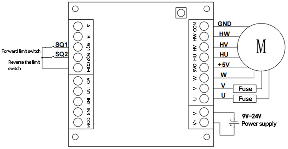
Application wiring diagram
Wiring method for the common model of the driver
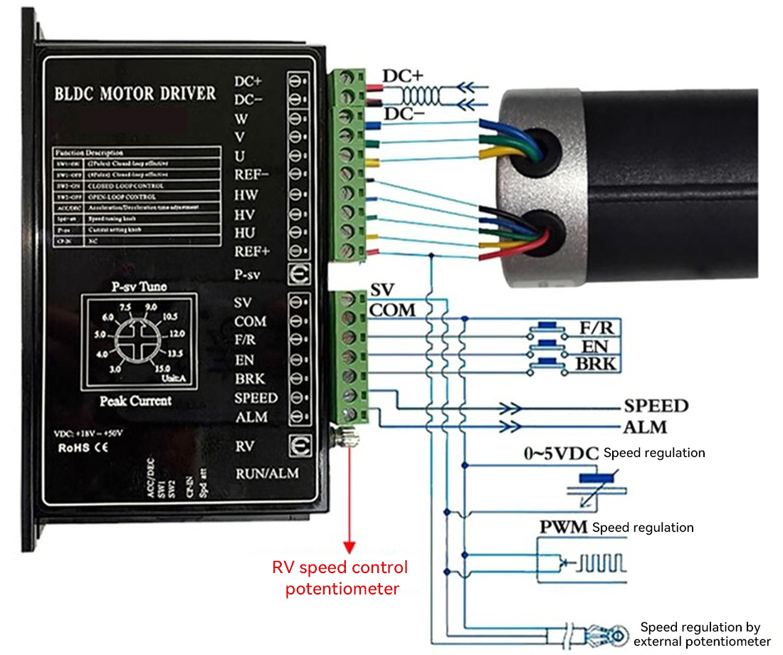
Wiring meter | ||
REF+ | RED | Thin line |
HU | YELLOW | |
HV | GREEN | |
HW | BLUE | |
REF- | BLACK | |
U | YELLOW | Thick line |
V | GREEN | |
W | BLUE | |
485 communication protocol driver wiring control
1.1 Product Dimensions
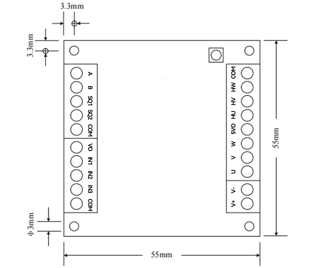
Figure 1.1 Product Size Definition
The size of the driver is shown in Figure 1.1. The dimensions are 55mmX55mmX17mm. The diameter of the installation hole is 3mm, and the distance from the center of the installation hole to the side is 3.3mm.
2.1.1 Key Usage
1) Through key operation, we can achieve one-click motor phase sequence learning and control mode switching. The functions of the keys under different operation modes are shown in Table 2.1.
Table 2.1 Usage of Keys | |||
操作方式 | 功能 | 说明 | 状态指示灯 |
Press briefly | Motor phase sequence learning | Learn to succeed | After the yellow light and the green light flash alternately six times, they remain on simultaneously for 1 second |
Learning failure | After the yellow light and the green light flash alternately for six times, the yellow light flashes continuously for three more times | ||
Hold for 1 second and then release | Switch control mode | Digital/analog signal control | The yellow light remains on constantly and the green light flashes at a frequency of 0.5/2Hz |
485 Communication control | The yellow light is always off and the green light flashes at a frequency of 0.5/2Hz | ||
Press and hold for 5 seconds and then release | Default communication parameters for communication | The baud rate is 9600bps, the check method is even check, and there is 1 stop bit | |
Press the button briefly and the motor enters the learning state. If the green and yellow status indicator lights alternate and flash six times and then remain on simultaneously for 1 second, the learning is successful. If the green and yellow lights of the status indicator light alternate and flash six times, and then the yellow light flashes continuously for three times, the learning has failed.
Press and hold the key for 1 second and then release it to achieve the switching between digital/analog signal control and 485 control. When the driver is in the digital/analog signal control mode, the yellow status indicator light remains on constantly and the green light flashes at a frequency of 0.5/2Hz. When the driver is in 485 control mode, the yellow status indicator light is constantly off, and the green light flashes at a frequency of 0.5/2Hz.
Press and hold the key for 5 seconds and then release it. Communicate with the driver via RS485 using the Modbus-RTU communication protocol. The default baud rate for communication is 9600bps. The verification method is even check, with 1 stop bit.
Users can also configure the motor-related current under digital/analog signal control mode through the sample program of the PC that comes with this driver. The rated current of the motor is configured with 485, with a default of 7A and a maximum configurable of 10A. It is recommended that the maximum does not exceed 8A.
Note: The configuration of the motor's rated current should be consistent with the actual rated current of the motor; otherwise, it may lead to unstable speed regulation, slow response, fuse burnout, and even more serious consequences. The actual rated current of the motor can be obtained through the motor nameplate indication, data sheet and other means.
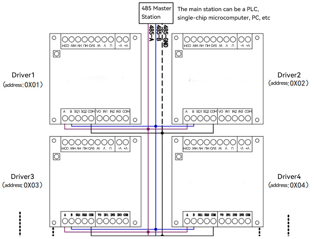
2) Connect the positive and negative terminals of the power supply to V+ and V- at the power interface of the driver respectively. Connect the 485 master station to the 485 interface of the driver in an A-A and B-B manner (for A more stable signal, the COM of the driver can be connected to the signal ground of the master station), as shown in Figure 3.5. Connect the power supply (Note: The voltage of the power supply should be consistent with the rated voltage of the motor, and the current it can provide should be greater than the rated current of the motor.
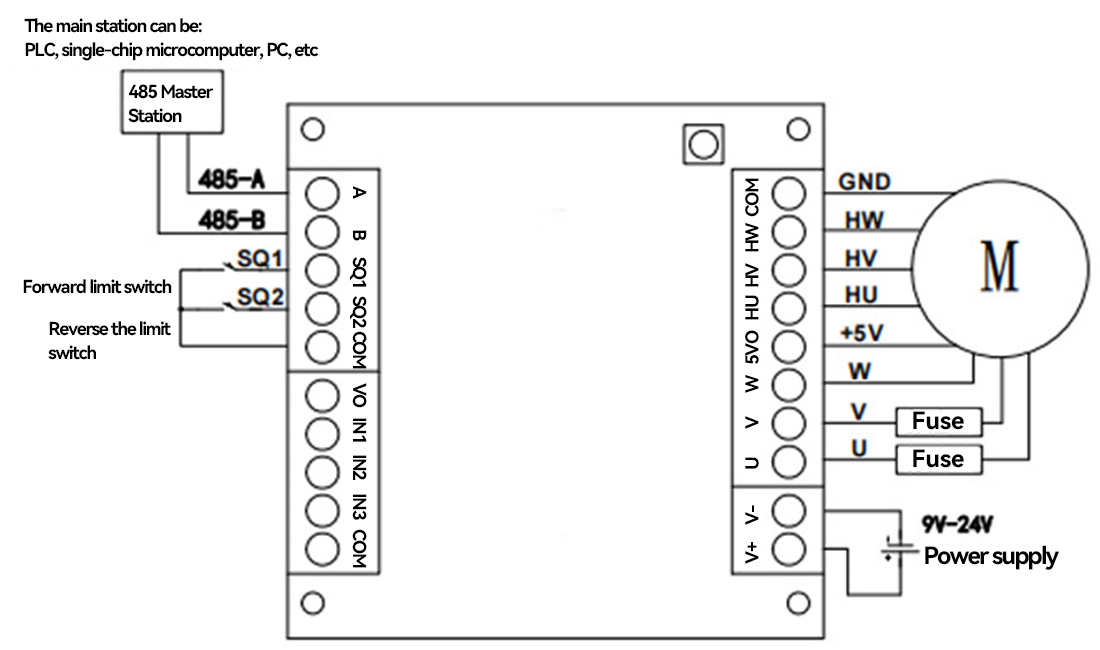
Figure 3.5 Wiring diagram of 485 communication power supply and motor
3) The operation keys configure the driver to 485 communication control mode. The yellow indicator light is always off and the green indicator light flashes at a frequency of 0.5/2Hz (for the key operation method, see Section 2.1.1).
4) Press and hold the key for 5 seconds and then release it. Communicate with the driver via RS485 using the Modbus-RTU communication protocol. The default baud rate for communication is 9600bps. The verification method is even check, with 1 stop bit. If the communication parameters have been reconfigured, please use the newly configured communication parameters for communication.
5) Configure the rated current and maximum load current of the motor through the 0x006a and 0x006b registers (see Section 6.3.4 for details). The configured rated current of the motor should be consistent with or slightly higher than the actual rated current of the motor. The maximum load current can be used to configure the maximum load/locked-rotor torque of the motor. If there are no specific requirements, It is usually the same as the rated current configuration (for the motor current configuration, please refer to Section 2.1.2). The rated current of the motor can be obtained from the nameplate of the motor or the data sheet. If the rated current of the motor cannot be determined, it can be estimated by dividing the rated power of the motor by the rated voltage and then by the motor efficiency. For a 12V motor, the efficiency can be taken as 50%, and for motors with a voltage of 24V or above, the efficiency can be taken as 70%.
This method uses a potentiometer to adjust the speed of the motor and a switch quantity/logic level to control the forward and reverse rotation and start and stop of the motor. The connection method of the single potentiometer speed regulation is shown in Figure 4.1. The two fixed terminals of potentiometer VR1 are connected to VO and COM, and the moving terminal is connected to IN1. When the moving terminal of the potentiometer slides from COM to VO, the motor speed increases from low to high. When the forward and reverse rotation and start and stop of the motor are controlled by switch quantities, switch K1 is connected between IN2 and COM to control the forward rotation of the motor; switch K2 is connected between IN3 and COM to control the reverse rotation of the motor. When using logic levels to control the forward and reverse rotation and start and stop of the motor, IN2 is connected to logic level DI1 to control the forward rotation of the motor, and IN3 is connected to logic level DI2 to control the reverse rotation of the motor. The limit switches SQ1 and SQ2 respectively limit the forward rotation and reverse rotation.
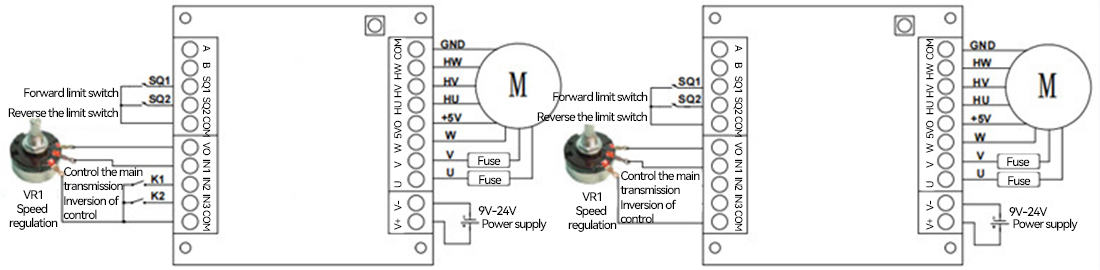
Figure 4.1 Connection method of the single potentiometer speed control switch quantity (left figure)/logic level (right figure) control mode
By configuring different types and polarities of digital signals (for how to configure the types and polarities of digital signals, see the System Parameter Configuration registers 0x0081 and 0x0085 in Section 6.3.5), we can achieve the start, stop and forward/reverse control of the motor through different operation methods on potentiometers, switch quantities and logic levels. The control logic is shown in Table 4.2. Limit the forward and reverse rotation of the motor.
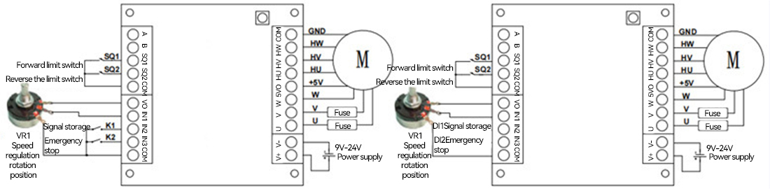
Figure 4.2 Connection method of single potentiometer position control (level-triggered) switch (left figure)/logic level (right figure)
By configuring different types and polarities of digital signals (for how to configure the types and polarities of digital signals, see Section 6.3.5 System Parameter Configuration Registers 0x0081 and 0x0085), we can achieve motor position adjustment, signal latches and emergency stops through different operation methods on potentiometers, logic levels and switch quantities. The control logic is shown in the table.
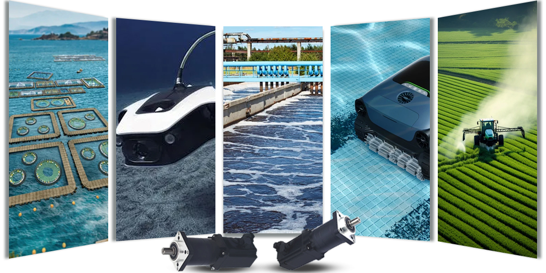
Application
It is widely applied in underwater robots, underwater photography robots, pipeline inspection robots, swimming pool cleaning robots, submersibles, underwater detectors, aquaculture monitoring equipment, chemical and sewage treatment, mines and dust environments, water conservancy and municipal engineering, agricultural and plant protection machinery.
Service
Dedicated service, along the way
Warranty worry-free, extended repair, often return to promote optimization, peace of mind choice, all in control.

Before the purchase of professional consultants rapid response, accurate recommendation products;

Purchase logistics is efficient, specially-assigned to ensure delivery;

After the purchase 7×24 hours customer service answer questions, engineers at any time to save the "machine";
After-sale guarantee
After-sales service: We provide comprehensive after-sales technical support, if you encounter any problems in the process of use, the professional after-sales engineer team will respond quickly, through telephone, mail or remote assistance, to provide you with detailed solutions. We also provide regular return visits to our products to understand how they are used and to collect your feedback in order to continuously optimize our products and services. In addition, in strict accordance with the quality assurance policy, we provide free repair or replacement services for products with quality problems during the warranty period, so that you have no worries.