
Product Description
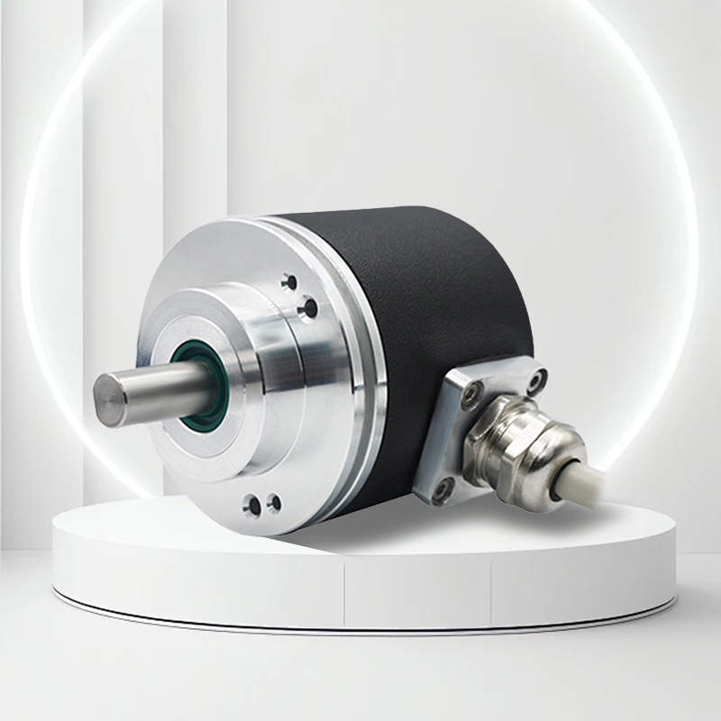
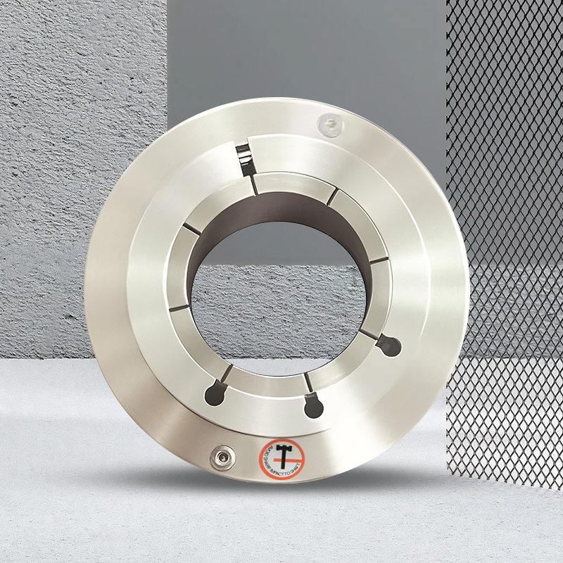
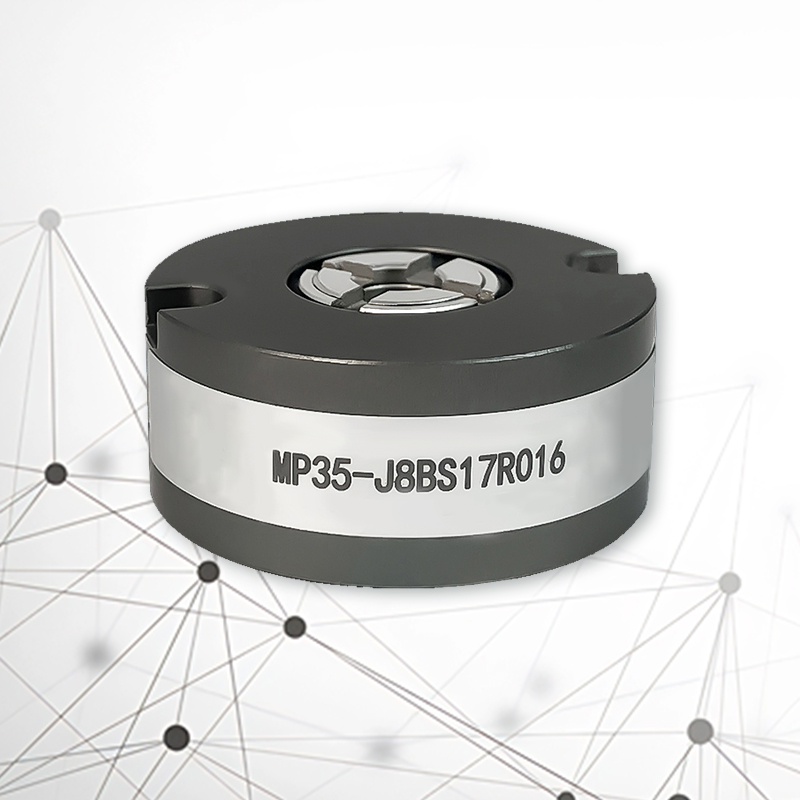
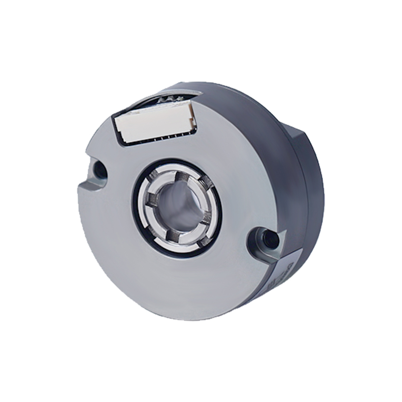
The MP35 absolute value encoder (through shaft) features a unique ultra-thin structure with concentric locking of the shaft and a single-bearing mechanical hard connection, making it a high-precision absolute value photoelectric encoder
Product Features |
|
Product parameters
Project | Main parameters |
Encoder type | Absolute value encoder |
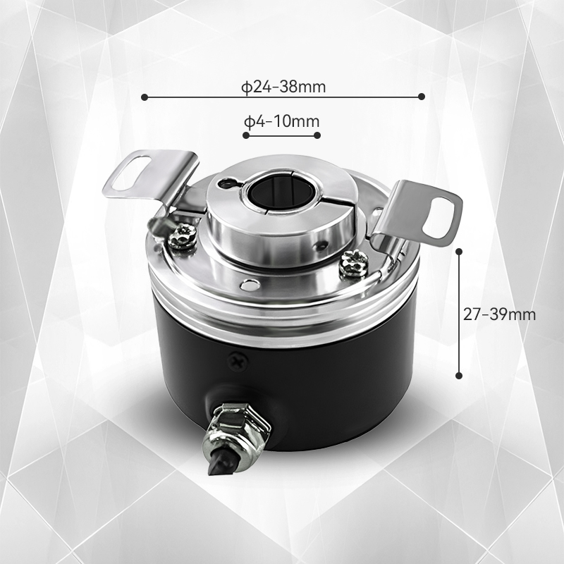
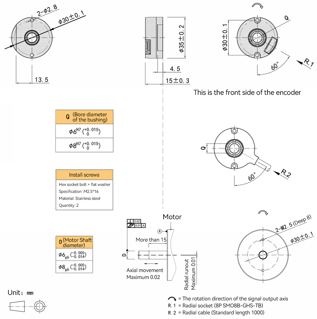
Outer diameter | 35mm |
Thickness | 15mm |
Shaft sleeve aperture | 6mm,8mm |
Resolution (Single circle) | 17 bits, 19 bits, 20 bits, 22 bits, 24 bits |
Communication format | BISS C&SSI |
Power supply voltage | DC5V |
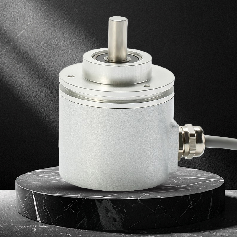
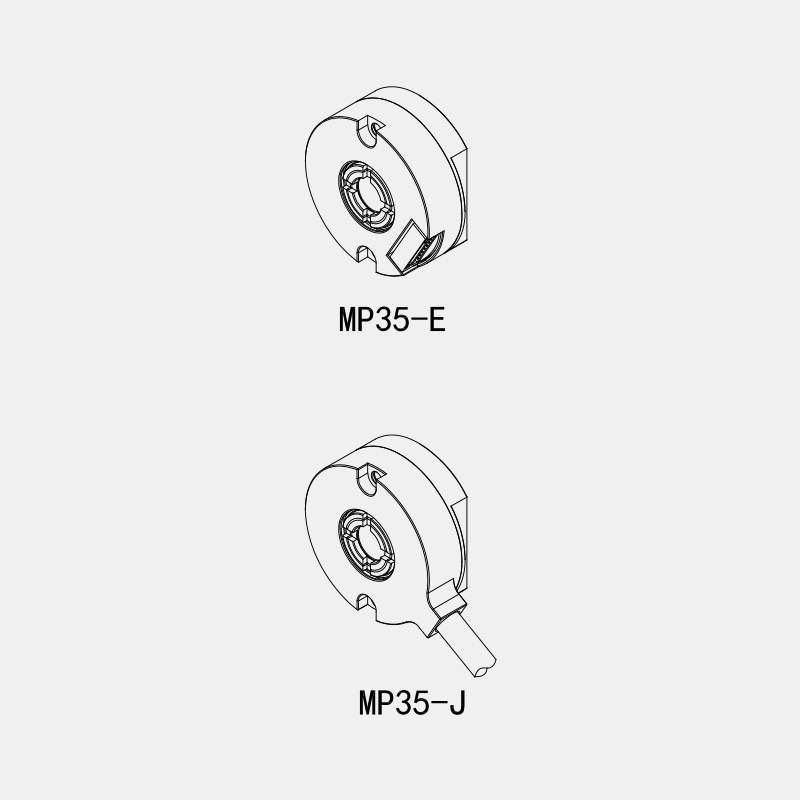
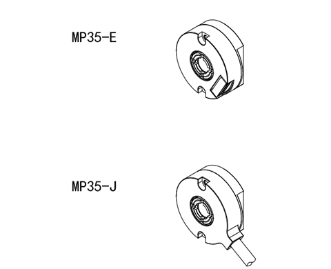
Connection interface | Radial socket & Radial cable |
Electrical interface | RS-485 |
Accuracy | ±80" |
Starting torque | Less than 5 × 10⁻³ n.m |
Inertial moment | Less than 1.5 × 10⁻⁶kg.m² |
Allowable force of the shaft | Radial 15N Axial direction: 5N |
Maximum allowable rotational speed | 6000RPM ; |
Ambient temperature | During operation :-20 to +95° C Storage temperature :-25 to +95° C |
Environmental humidity | During operation and storage: 35-85%RH(no condensation) |
Vibration | Amplitude: 0.75mm,5-55Hz, 2 hours in each of the three axes |
Impact | 490m/s ² for 11ms, three times in each direction |
shaft | Stainless steel |
Shell | Aluminum alloy |
Line length | 200-1000mm |
Protection grade | IP50 |
Packaging | Paper box packaging |
Instructions for Use
1. Selection Guide | ||||||||||||||||
Model composition (Selection parameters) | ||||||||||||||||
MP35- | E | 8 | B | 24 | R | - | 000 | |||||||||
↑ | ↑ | ↑ | ↑ | ↑ | ↑ | ↑ | ↑ | ↑ | ||||||||
Product model | Connection interface: | Shaft diameter: (through) | Communication format: | Resolution: | Electrical interface: | Power supply voltage: | Special specification: No indication =① | Management Number | ||||||||
Special Specifications: ①.IP=50; The length of the cable is 1m. If the length needs to be changed by C+ the number, the maximum length will be 10M(denoted as C10). | ||||||||||||||||
2、Resolution
Single lap (ST) | |
17Bits 217(0~+131071) | The standard product is below 24Bits and can be expanded up to 32Bits at most |
19Bits 219(0~+524287) | |
20Bits 220(0~+1048575) | |
22Bits 222(0~+4194303) | |
24Bits 224(0~+16777215) | |
3、Specification parameters
Name | Parameters | Remarks |
Scanning principle | Optoelectronics | |
Accuracy | ±80" | |
Response rotation speed | During normal action: 6000min⁻¹ | |
RMS position signal noise | ±2@18 Bits/r | |
Communication format | BiSS_c(binary) | Refer to the BiSS_C standard |
SSI(Binary/Gray Code) | Refer to the SSI standard | |
Communication clock frequency | ≤10 MHz(BiSS) or ≤5 MHz(SSI) | |
Resolution | 24 Bits can be expanded up to 32 Bits at most | |
Startup time | Typical value: 13 ms | |
Absolute position sampling period | ≤75ns | |
Permissible rotational speed | ≤32200 r/min | Restricted by the mechanical speed limit |
Electrical connection | Radial socket & Radial cable | |
Cable | Twisted pair cable | |
Cable length | 200mm-10000mm | |
Internal single-loop position update rate | 15000kHz | The access rate is limited by the communication frequency |
Internal multi-circle position update rate | 11.5 kHz | |
Temperature alarm limit value | -20℃ to 95℃ |
4、Mechanical specifications
Name | Parameters | Remarks |
Mechanical connection | It is clamped and locked with the shaft and rigidly connected and fixed on the motor platform | |
Axial aperture | φ6mm, φ8mm(through) | |
Shaft material | Stainless steel | |
Starting torque | Below 5×10⁻³N·m | |
Inertial moment | Less than 1.5×10⁻⁶kg·m² | |
Allowable force of the shaft | Radial 15N Axial direction: 5N | |
Maximum allowable rotational speed | ≤6000 rpm | |
Shell material | Aluminum alloy | |
weight | About 70g |
5、Environmental parameters
Name | Parameters |
Ambient temperature | Operating temperature: -20 to +95℃ |
Storage temperature: -25 to +95℃ | |
Environmental humidity | During operation and storage: 35-85%RH(no condensation) |
Vibration | Amplitude: 0.75mm,5-55HZ, 2 hours in each of the three axes |
Impact | 490m/s²11ms, three times in the X,Y, and Z directions |
Protection grade | IP50 |
6、Electrical characteristics: Absolute maximum rated parameter range
Symbol | Explanation | The smallest | The largest | Unit |
Vcc | Working voltage | -0.3 | +6 | V |
VBAT | Backup voltage | -0.3 | +6 | V |
TSTG | Storage temperature | -25 | +95 | ℃ |
TJ | Node temperature | -50 | +125 | ℃ |
7、Electrical parameters
Symbol | Explanation | The smallest | Typical value | The largest | Unit |
Vcc | The supply voltage is DC5V | 4.75 | 5 | 5.5 | V |
The power supply voltage is DC8-30V | 7.75 | 30 | 32 | V | |
IDD | Working current | 一 | 一 | 120 | mA |
VBAT | Backup voltage ① | 3 | 3.6 | 4.2 | V |
I(BAT) | Backup current | 一 | 一 | 35 | uA |
fBISS ② | BISS communication clock frequency | — | 一 | 10 | MHz |
SSI communication clock frequency | — | 一 | 5 | MHz | |
Ta | Working environment temperature | -20 | 一 | +95 | ℃ |
①For the power supply sequence of multi-turn encoders, please make sure that the battery is powered on first and then the system power is connected.
② For details, see the BiSS_c and SSI standards.
8、Basic dimensions and installation shaft specifications
9、Interface definition function and socket pin definition (Radial socket)
Socket pin number | Signal name | Function | Twisted pair cable | |
BISS_C single lap | SSI single lap | |||
Pin 1 | Up | Up | Positive pole of the power supply |
|
Pin 2 | Un | Un | Negative pole of the power supply | |
Pin 3 | SL- | DATA- | Data signal |
|
Pin 4 | SL+ | DATA+ | Data signal | |
Pin 5 | MA- | CLOCK- | Clock signal |
|
Pin 6 | MA+ | CLOCK+ | Clock signal | |
Pin 7 | 一 | — | 一 | |
Pin 8 | 一 | 一 | 一 | |

10、Socket definition
Unit:mm
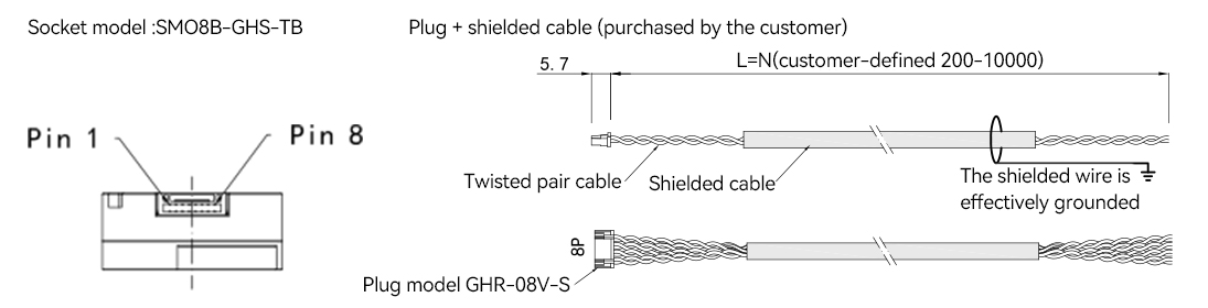
11、Function and Line Color Definition (Radial Cable)
Line color | Signal name | Function | Twisted pair cable | |
BISS_C single lap | SSI single lap | |||
Red | Up | Up | Positive pole of the power supply |
|
Black | Un | Un | Negative pole of the power supply | |
White | SL- | DATA- | Data signal |
|
White/Black | SL+ | DATA+ | Data signal | |
Green | MA- | CLOCK- | Clock signal |
|
Green/Black | MA+ | CLOCK+ | Clock signal | |
12、Radial cable illustration
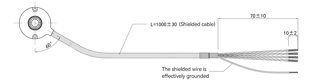
Unit:mm
13、Electrical connection
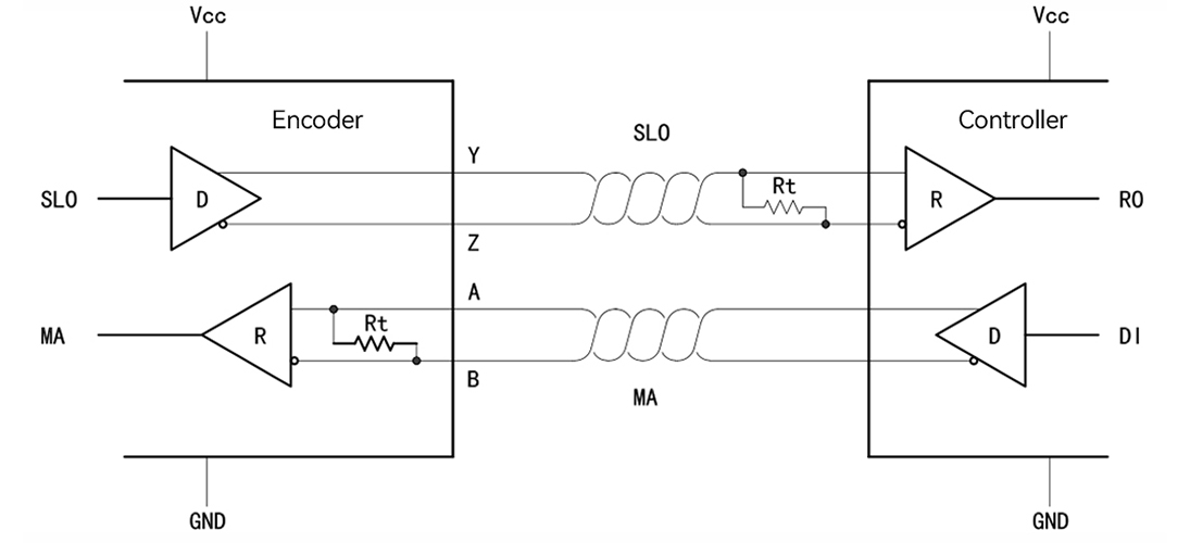
Figure 1 Point-to-point wiring method
Note: Both the MA and SLO lines are differential twisted-pair transmission cables, compatible with RS422. The termination resistor of the MA
transmission line has been integrated inside the encoder.
14、BiSS_C communication
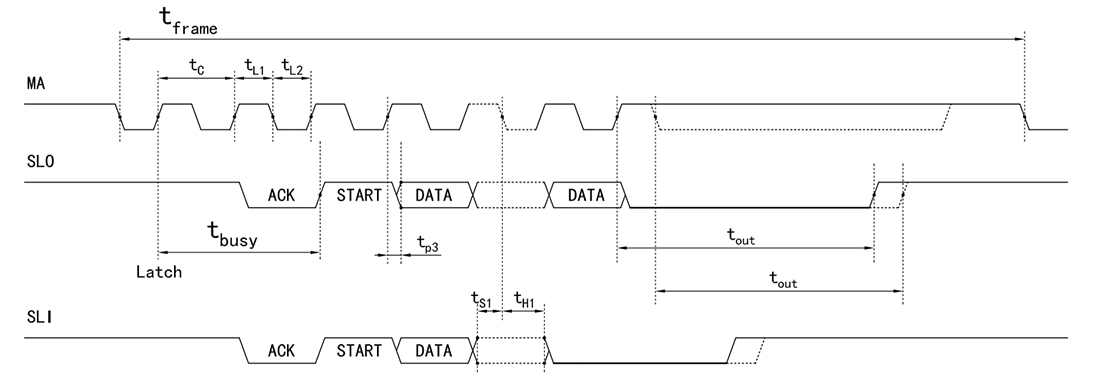
Figure 2 BiSS_C timing diagram
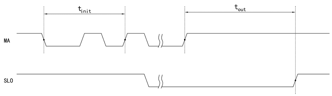
Figure 3 BiSS_c(SSI) slave timeout timing series
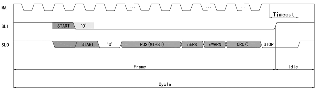
Figure 4 BiSS data frame structure
15、SSI Communication
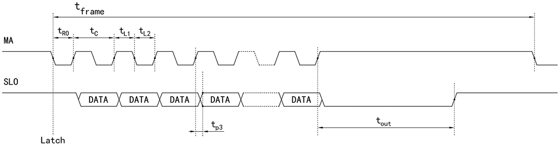
Figure 5 SSI timing diagram
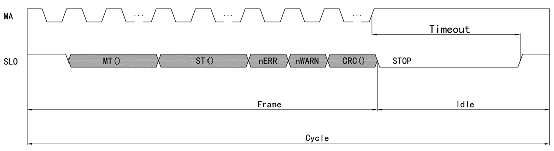
Figure 6 SSI data frame structure
The data frame is composed of the frame structure and the data to be transmitted. The data transmission sequence is to output the MSB as the priority, the error bit and alarm bit as the low valid, and the check bit as the flipped level output. The specific data composition is shown in the following table:
Bits No. | Data segment | Explanation |
[55:32] | MT[23:0] | Record the cumulative number of turns that the encoder has run after being powered on |
[31:8] | ST[23:0] | The current absolute position data |
[7] | nERR | Incorrect bit, low valid |
[6] | nWARN | Alarm position, low effective |
[5:0] | CRC[5:0] | The CRC polynomial of the check bit is 0x43, and the initial value is 0(output at the flip level). |
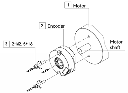
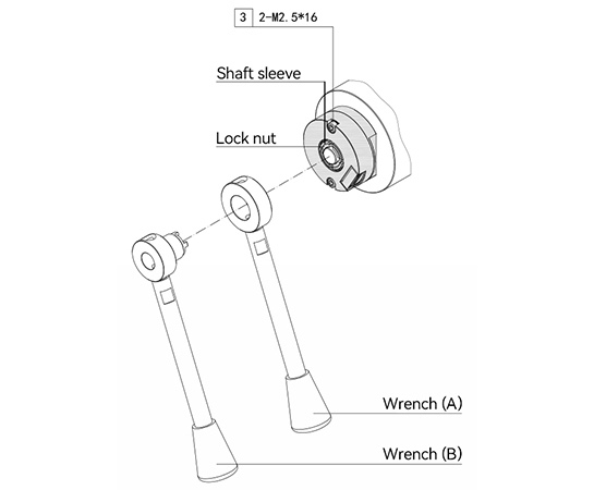
16、Installation steps
The first step |
|
| Step Two |
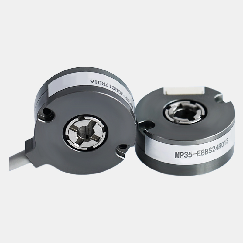
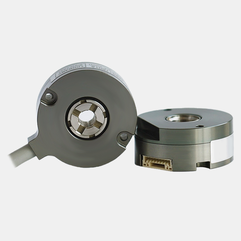
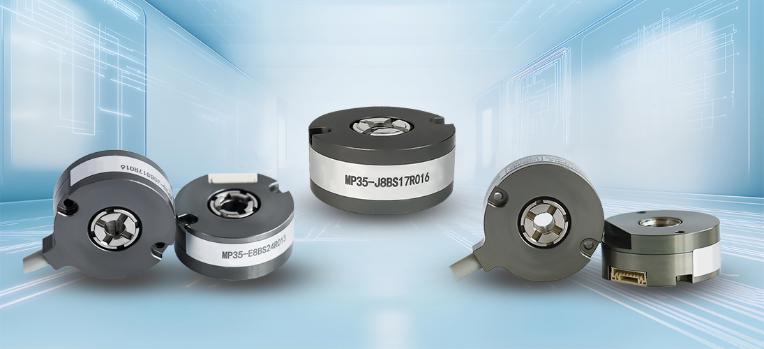
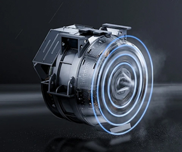
Product Display

High speed, high pulse, high precision, resistance to high and low temperatures, and high stability
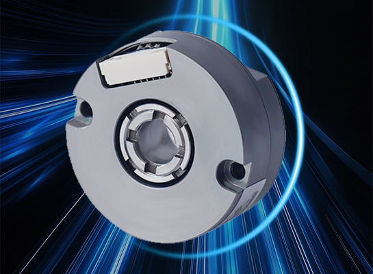
Unique mechanical structure, compact and ultra-thin design; The concentric locking structure of the shaft, the independently designed grating code disk and assembly process, and the circuit adopts anti-interference measures
Application Cases
Hollow encoders are widely used in the field of industrial automation, such as position control of machine tools and robots. In the power industry, it is used for monitoring the rotational speed and position of generators and steam turbines; It can also be used in elevators, textile machinery, etc., to achieve precise positioning and speed regulation, and improve the performance and degree of automation of the equipment.


Service
1. Precautions for Using Encoders
A place where the ambient temperature must not exceed the storage temperature; A place where the relative humidity must not exceed the storage
humidity; It cannot be in places with sharp temperature changes and fogging. Places close to corrosive gases and flammable gases; Stay away from
places with a lot of dust, salt and metal powder. Stay away from places where water, oil and medicine are used; Excessive vibration and shock can be
transmitted to the main body
2. Precautions for Installing Encoders
Electrical components must not be subjected to overvoltage or other phenomena. Please conduct static electricity assessment of the setting
environment, etc. Do not allow the motor power line to approach the encoder. The FG wire of the motor and the FG wire of the mechanical device
must be reliably grounded. Since the shielded wire is not connected to the encoder body, the shielded wire must be effectively connected to the
ground at the user end
3. Precautions on Wiring
When used at the specified power supply voltage, please pay attention to the decrease in power supply voltage amplitude caused by the long wiring.
Please do not use the encoder line and other power lines in the same pipe or bundle them in parallel. Please use twisted-pair wires for the signal line
and power line of the encoder. Please do not apply excessive force to the wire harness of the encoder, as there is a risk of wire breakage
4. Regarding the warranty of the encoder
Within twelve months of purchasing the products of our company, if any malfunction occurs due to correct use in accordance with the precautions
in the user manual, warning signs, etc., free warranty will be provided.
The following situations will be charged even within the warranty period: (Freight is at your own expense)
①. Faults and damages caused by the user landing during transportation or handling or improper installation;
②. Faults of this product caused by the machine connected to it;
③. Faults and damages caused by fire, salt water, corrosive gases, abnormal voltages, and other natural disasters such as earthquakes, lightning, wind, and floods;
④. Repair, adjustment or modification without the permission of our company (the label is not present or the outer cover is removed by oneself).
⑤. Malfunctions that occur when the user does not follow the usage methods and precautions described in the user manual.
⑥. Except where there are other agreements signed with the client.