
Product Description
DC series
Dc servo driver
Fast | Intelligent | Accurate
Functional Features
Digital control and technical features | |
Digital control loop | Current, speed and position, 100% digital loop control; Dual position loop control using the second encoder input |
Sampling frequency (time) | Current loop :15KHZ(66.7μs) Speed/Position loop :3KHZ(330μs) |
Communication | Sinusoidal magnetic field directional control or trapezoidal control from HALL to brushless motors |
Modulation | Space vector PWM modulation with center weighting |
Broadband | The current loop is generally 2.5KHZ and varies with parameter adjustments and load inductance |
HV compensation | Changing the bus voltage (HV) does not affect the bandwidth |
Minimum load inductance | 50 mH wire inductor |
DC Series Technical Specifications |
◆ Control mode: Position, speed, torque; |
Electrical standard specifications | ||||
Position control | Instruction control mode | Servo enable, external reset, forward/reverse limit, motor operation stop, high-speed analog acquisition control, PWM synchronous signal input, high-speed pulse input, etc | ||
Input signal | Pulse instruction | Input pulse pattern | It includes three instruction forms: "direction + pulse", "A and B phase orthogonal pulse", and "CW/CCW pulse" | |
Signal format | Differential input, collector open circuit | |||
Maximum pulse frequency | Differential input :(maximum 2 Mpps) Collector open circuit :(maximum 500Kpps) | |||
Simulation instruction | Voltage range | Input voltage range ±10V | ||
Input impedance | Differential input impedance =5 KΩ | |||
Speed control | Instruction control mode | PWM, ±10V analog quantity, function generator, software programming | ||
Input signal | PWM | Polarity | PWM =0-100%, polarity =1/0 | |
Non-polarity | PWM =50% +/-50% | |||
Frequency range | Minimum 1kHz, maximum 100kHz | |||
Minimum pulse width | 220ns | |||
Simulation instruction | Voltage range | Input voltage range ±10V | ||
Input impedance | Differential input impedance =5 KΩ | |||
Current control | Instruction control mode | PWM, ±10V analog quantity, function generator, software programming | ||
Input signal | PWM | Polarity | PWM =0-100%, polarity =1/0 | |
Non-polarity | PWM = 50% +/-50% | |||
Frequency range | Minimum 1kHz, maximum 100kHz | |||
Minimum pulse width | 220ns | |||
Simulation instruction | Voltage range | Input voltage range ±10V | ||
Input impedance | Differential input impedance =5 KΩ | |||
I/O signal | Digital input IN | The number of ports | 10(Among them, IN6, IN7, IN8, IN9 and IN10 are high-speed ports, and IN5 is internally used for motor temperature protection) | |
Signal format | NPN(Effective at low level) | |||
Settable functions | Servo enable, external reset, forward/reverse limit, motor operation stop, high-speed analog acquisition and control, PWM synchronous signal input, high-speed pulse input, etc | |||
Digital output OUT | The number of ports | 3 | ||
Signal format | NPN(effective at low level), capable of withstands a maximum current of 300 madC and a maximum voltage of 30Vdc | |||
Settable functions | Fault signal, brake control, PWM synchronization signal, custom event, trajectory status, position trigger, program control | |||
Function | LED indication | Status indication, CAN network indication | ||
Communication function | RS-232 | Baud rate | 9600-115200. | |
Agreement | Full-duplex mode, ASCII or binary format | |||
CAN | Baud rate | 20kbit/s-1Mbit/s | ||
Agreement | Canopen Application Layer DS-301V4.02 | |||
Equipment | DSP-402 device drive and motion control | |||
Protection function | Overvoltage, overcurrent, undervoltage, overload, overheating, encoder abnormality, excessive position tracking error and other protections | |||
Usage environment | Installation location | No corrosive gases, flammable gases, etc | ||
Altitude | Less than 1,000 meters | |||
Altitude | -20℃ to +40℃ | |||
Humidity | 5% to 95%RH, no water droplets condense | |||
Vibration resistance/shock resistance strength | Less than 4.9 m/s ² / less than 19.6 m/s ² | |||
Feedback | Digital A/B orthogonal encoder (-E, maximum rate 5M line/s) | |||
Auxiliary encoder input/output (Full closed-loop control /-OP) | ||||
Analog sin/cos encoder (-s) is optional | ||||
A resolver (-R) is optional | ||||
Digital Hall (-H(U/V/W, 120-degree electrical phase difference)) | ||||
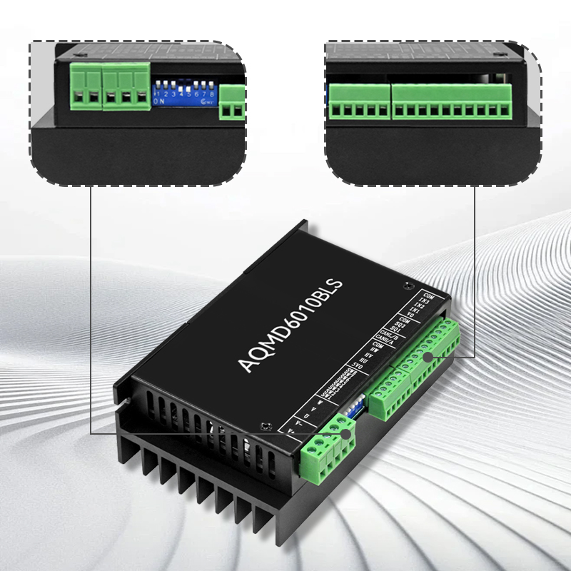
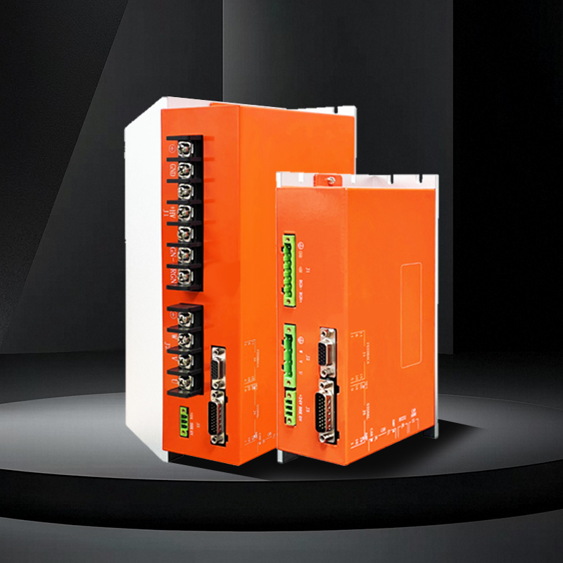
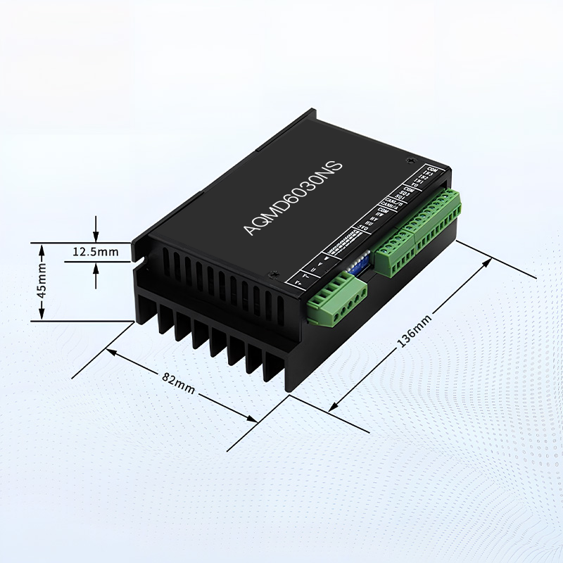
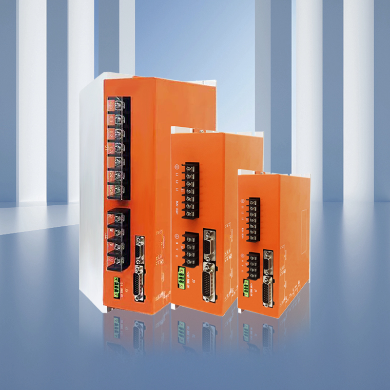
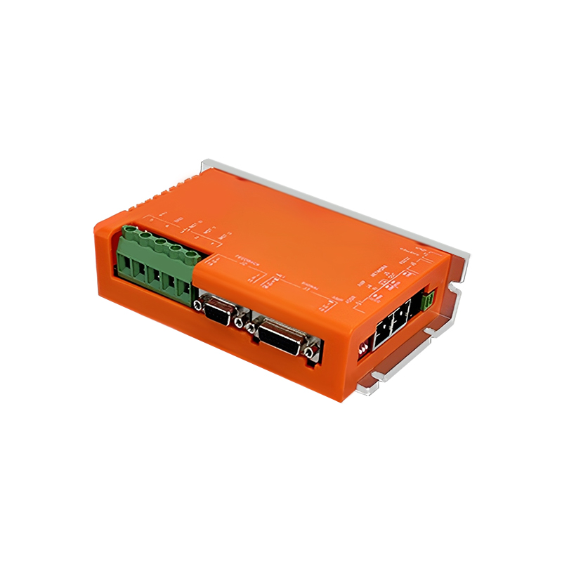
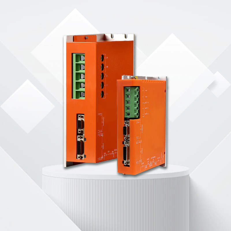
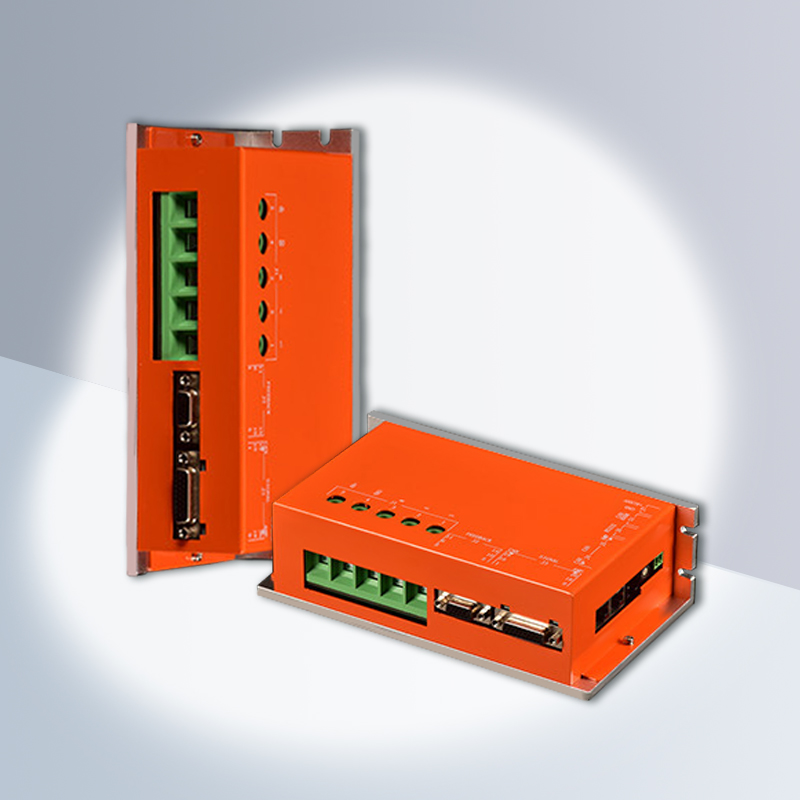
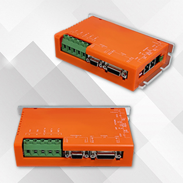
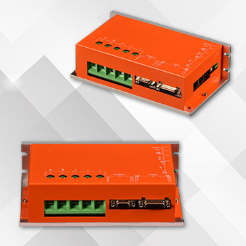
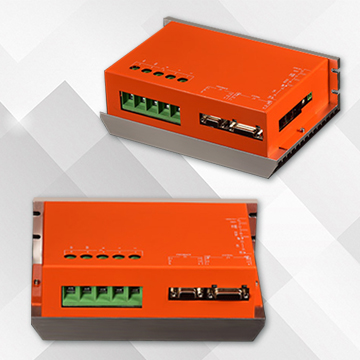
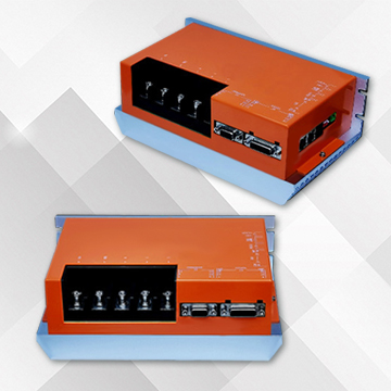
Product Display
REAL PICTURE DETAILS DISPLAY
2A-50A
75A 100A 150A
200A
300A-MD
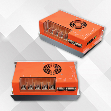
300A-LG 350A
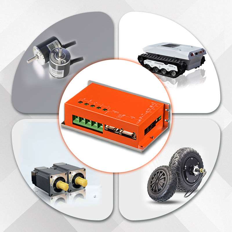
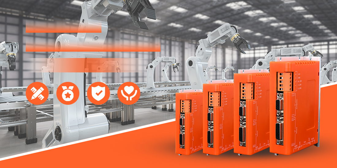
Application
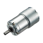
Servo drivers are applied in various servo motors, robot fields, new energy fields, automation fields, AGV automotive industries, and control systems. They can convert the input voltage signal into mechanical output on the motor shaft, drive the controlled components, and thereby achieve the control purpose.
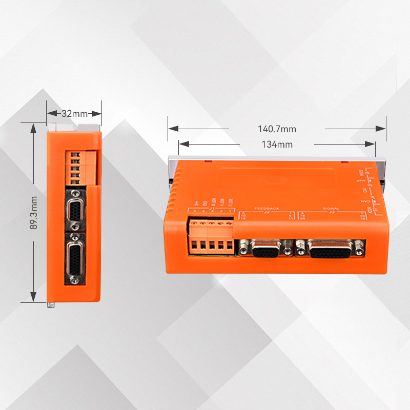
Dimensional drawing
DC series external dimensions drawing:
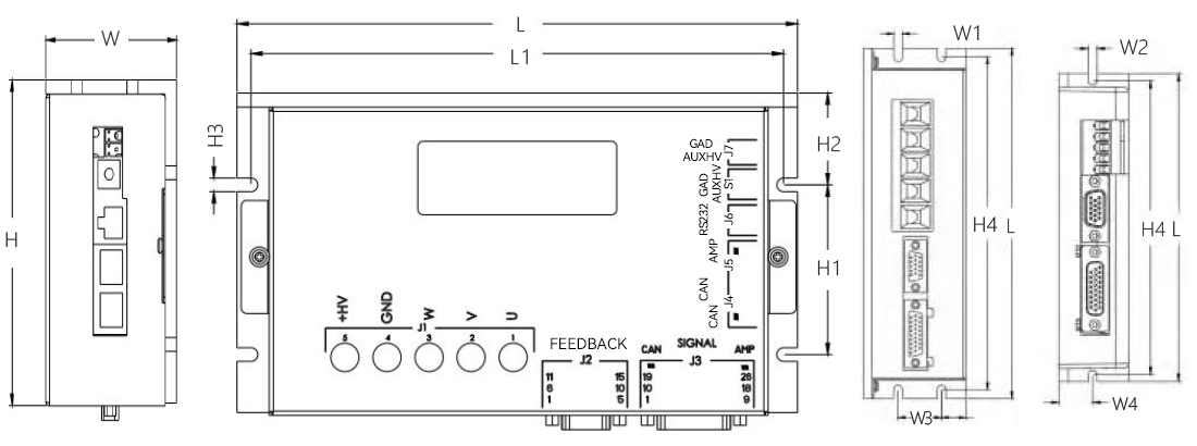
Model | L | L1 | W | W1 | W2 | W3 | W4 | H | H1 | H2 | H3 | H4 |
DCPC-2A ~24A | 141 | 134 | 32 | / | 4.5 | / | 15. 5 | 89 | 51 | 18 | 4.5 | 134 |
DCPC-30A~50A | 167 | 160 | 35 | / | 2-4.5 | / | 19. 5 | 100 | 51 | 22 | 4-4.5 | 160 |
DCPC-75A100A | 200 | 190 | 59 | 4-5.0 | / | 25 | / | 114 | 60 | 32.5 | 4-4.8 | 190 |
DCPC-100AF | 200 | 190 | 59 | 4-5.0 | / | 25 | / | 114 | 60 | 32.5 | 4-4.8 | 190 |
DCPC-150A | 221 | 211 | 59 | 5 | / | 25 | / | 140 | 60 | 45 | 4.8 | 211 |
DCPC-150AF | 221 | 211 | 59 | 5 | / | 25 | / | 140 | 60 | 45 | 4.8 | 211 |
DCPC-200A | 221 | 211 | 85 | 5 | / | 25 | / | 140 | / | / | / | 211 |
DCPC-300A | 221 | 211 | 85 | 5 | / | 25 | / | 140 | / | / | / | 211 |
Model Description
DC | PC | -90 | 12 | -OP | E | MD | ||||||||||||||||||
Series | Special requirements | |||||||||||||||||||||||
DC/DH/DE/DE2/BC/BC2 | MD: Small size LG: Large size | |||||||||||||||||||||||
RTR: Reduce temperature rise | ||||||||||||||||||||||||
Input instructions | GT: Green terminal type (BO) F: With fan | |||||||||||||||||||||||
P: Pulse A: Analog R:RS485 | B: With braking unit (DH DC) | |||||||||||||||||||||||
C:CANopen E:EtherCAT | ||||||||||||||||||||||||
Feedback | ||||||||||||||||||||||||
Power supply voltage | E: Incremental A/B orthogonality | |||||||||||||||||||||||
090:18-90VDC 180:18-180VDC | A: The absolute value of photoelectric is 17 bits | |||||||||||||||||||||||
135:18-135VDC 300:300VDC 540:540VDC | H: Digital Hall; S: Analog sine and cosine | |||||||||||||||||||||||
Rated current | Special function | |||||||||||||||||||||||
16:16Amps(11Arms) 50:50Amps(35Arms) | OP: Pulse output | |||||||||||||||||||||||
150:150Amps(105Arms) | HUB: Servo hub (BC) | |||||||||||||||||||||||
Product parameters
Summary table of Driver Specifications | ||||||
Driver model | Power supply voltage | Amps(Arms) | Apk(Arms)6S | Feedback type | External dimensions | Weight |
DCPC-09002-OPE | 18 ~ 90VDC | 2A(1.4A) | 6A(4.2A) | Incremental | 141*90*32mm | 0.35kg |
DCPC-09003-OPE | 3A(2.1A) | 9A(6.3A) | ||||
DCPC-09004-OPE | 4A(2.8A) | 8A(5.6A) | ||||
DCPC-09005-OPE | 5A(3.5A) | 10A(7A) | ||||
DCPC-09008-OPE | 8A(5.6A) | 24A(16A) | ||||
DCPC-09016-OPE | 16A (11A) | 48A(33A) | ||||
DCPC-09024-OPE | 24A(16A) | 50A(35A) | ||||
DCPC-09030-OPE | 30A(21A) | 60A(42A) | 167*100*35mm | 0.45kg | ||
DCPC-09040-OPE | 40A(28A) | 80A(56A) | ||||
DCPC-09050-OPE | 50A(35A) | 100A(70A) | ||||
DCPC-09075-OPE | 75A(52A) | 150A(105A) | 200*114*59mm | 1.10kg | ||
DCPC-090100-OPE | 100A(70A) | 200A(140A) | ||||
DCPC-090125-OPE | 125A(88A) | 250A(177.5A) | ||||
DCPC-090150-OPE | 150A(105A) | 250A(175A) | 221*140*59mm | 1.45kg | ||
DCPC-090200-OPE | 200A(140A) | 300A(210A) | 221*140*85mm | 1.8kg | ||
DCPC-090300-OPE-MD | 300A(210A) | 420A(294A) | ||||
DCPC-090300-OPE-LG | 300A(210A) | 420A(294A) | 265*140*85mm | 2.3kg | ||
DCPC-090350-OPE | 350A(250A) | 470A(330A) | ||||
DCPC-18002-OPE | 18 ~180VDC | 2A(1.4A) | 6A(4.2A) | 167*100*35mm | 0.45kg | |
DCPC-18003-OPE | 3A(2.1A) | 9A(6.3A) | ||||
DCPC-18004-OPE | 4A(2.8A) | 8A(5.6A) | ||||
DCPC-18005-OPE | 5A(3.5A) | 10A(7A) | ||||
DCPC-18008-OPE | 8A(5.6A) | 24A(16A) | ||||
DCPC-18016-OPE | 16A (11A) | 48A(33A) | ||||
DCPC-18024-OPE | 24A(16A) | 50A(35A) | ||||
DCPC-18050-OPE | 50A(35A) | 100A(70A) | 200*114*59mm | 1.10kg | ||
DCPC-18075-OPE | 75A(52A) | 150A(105A) | ||||
DCPC-180100-OPE | 100A(70A) | 200A(140A) | 221*140*59mm | 1.45kg | ||
DCPC-180150-OPE | 150A(105A) | 250A(175A) | 265*140*85mm | 2.3kg | ||
DCPC-135100-OPE | 18 ~ 135VDC | 100A(70A) | 200A(140A) | 221*140*59mm | 1.45kg | |
DCPC-135150-OPE | 150(105A) | 250(175A) | 221*140*85mm | 1.8kg | ||
DCPC-135200-OPE | 200A(140A) | 300A(210A) | ||||
DCPC-125300-OPE | 300A(210A) | 420A(294A) | 265*140*85mm | 2.3kg | ||
Note: 1. The supply voltage of the driver must be greater than or equal to the rated voltage of the motor; | ||||||
Application wiring diagram
DC series system wiring diagram:
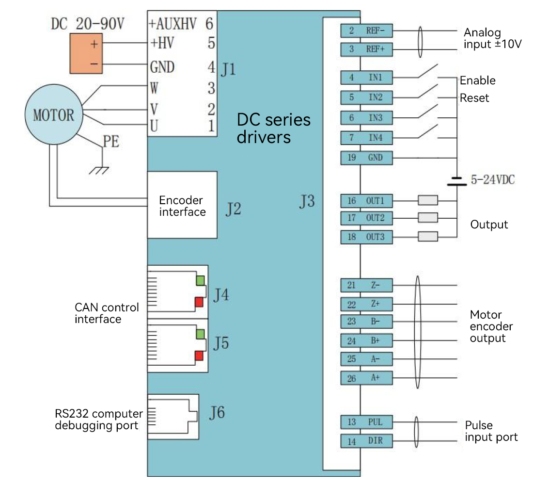
Explanation:
1. The inputs IN1 and IN2 IN3, IN4, IN5, IN11, IN12 is common port can receive signals NPN and PNP, the highest input voltage 24 v
2.IN6,IN7,IN8,IN9, and IN10 are high-speed input ports with a maximum input voltage of 5V
3.+AUXHV is the auxiliary power supply. It can be connected if necessary. If connected, when +HV disconnects the power supply and +AUXHV is powered on, communication remains, but there will be no action when sending commands
DC series terminal definition
Definition of DC series terminals | ||
For debugging J6 RS-232 | ||
Foot position | Definition |
|
1 | NO Connection | |
2 | RxD | |
3 | Signal Ground | |
4 | Signal Groudn | |
5 | TxD | |
6 | NO Connection | |
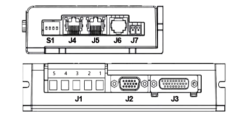
J4-J5 CAN communication link | J1 motor power supply | |||
Foot position | Definition | Foot position | Definition | |
1 | CAN_H | 1 | U | |
2 | CAN_L | 2 | V | |
3 | CAN_GND | 3 | W | |
4 | No Connection | 4 | 0V | |
5 | Reserved | 5 | DC20-90 | |
6 | (CAN_SHLD)1 | |||
7 | CAN_GND | 6 | Auxiliary power supply | |
8 | (CAN_V+)1 | |||
J3 control signal terminal | |||||
Foot position | Definition | Foot position | Definition | Foot position | Definition |
1 | The Earth | 10 | [IN6] Custom | 19 | 0V |
2 | Analog input - | 11 | [IN7] Custom | 20 | +5V |
3 | Analog input + | 12 | [IN8] Custom | 21 | Pulse output Z- |
4 | Enable | 13 | [IN9] Custom | 22 | Pulse output Z+ |
5 | [IN2] Custom | 14 | [IN10] Custom | 23 | Pulse output B- |
6 | [IN3] Custom | 15 | [IN5] Motor temperature | 24 | Pulse output B+ |
7 | [IN4] Custom | 16 | [OUT1] Custom | 25 | Pulse output A- |
8 | [IN 11] Custom | 17 | [OUT2] Custom | 26 | Pulse output A+ |
9 | [IN12] Custom | 18 | [OUT3] Custom | ||
J2 motor encoder feedback | |||||
Foot position | Definition | Foot position | Definition | Foot position | Definition |
1 | SIN+ | 6 | V+ | 11 | B - |
2 | SIN- | 7 | Z- | 12 | B+ |
3 | U+ | 8 | Z+ | 13 | A- |
4 | +5 V | 9 | W+ | 14 | A+ |
5 | 0V | 10 | COS+ | 15 | COS- |
The SW dip switch corresponds to the station number | |
SW Switch serial number | Corresponding station number |
1 | 1 |
2 | 2 |
3 | 4 |
4 | 8 |
Service
Dedicated service, along the way
Warranty worry-free, extended repair, often return to promote optimization, peace of mind choice, all in control.

Deliver on time Technical support Customer service After-sales service Logistics Payment security
After-sale guarantee
After-sales service: We provide comprehensive after-sales technical support, if you encounter any problems in the process of use, the professional after-sales engineer team will respond quickly, through telephone, mail or remote assistance, to provide you with detailed solutions. We also provide regular return visits to our products to understand how they are used and to collect your feedback in order to continuously optimize our products and services. In addition, in strict accordance with the quality assurance policy, we provide free repair or replacement services for products with quality problems during the warranty period, so that you have no worries.