
Product Description
Model :AQMD2408NS-MBE |
|
The AQMD NS series motor driver adopts advanced precise detection technology of motor loop current, self-detection technology of brushed DC motor speed, regenerative current constant current braking (or braking) technology and powerful PID regulation technology, which can perfectly control the motor start-up, braking (braking), commutation process and locked rotor protection. The motor has a short response time and a small recoil force. Real-time monitoring of output current prevents overcurrent, effectively protecting the motor and driver. | |
Functional Features
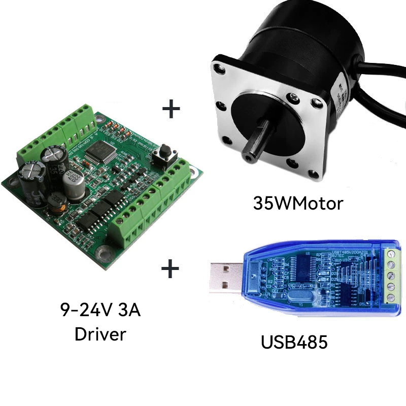
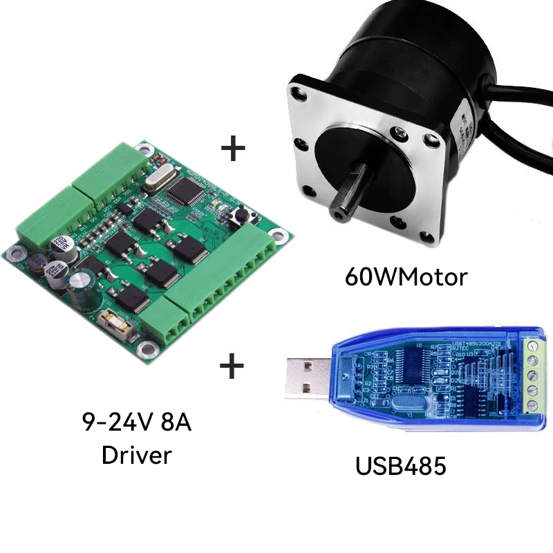
◆ Supported voltage: 9V to 24V;
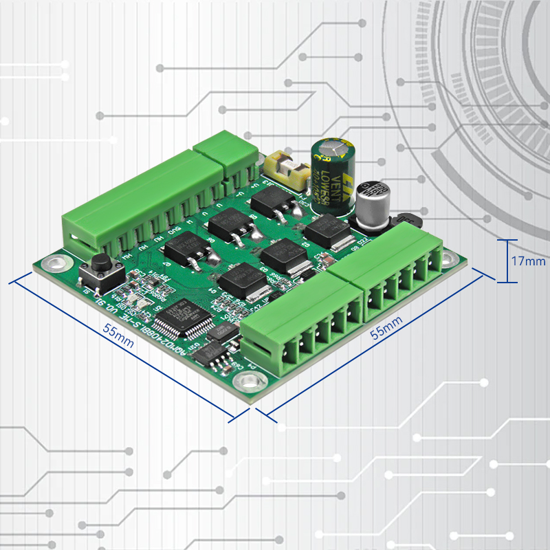
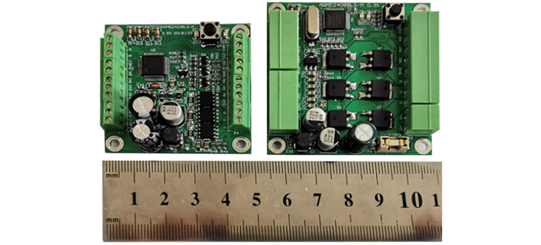
◆ Compact size: The rated 3A model is only 4.5x4.5cm, and the rated 24V 8A model is only 5.5x5.5cm.
◆One-click motor phase sequence adaptation, temperature monitoring, maximum output of twice the rated current, and large starting torque
◆Support the MODBUS-RTU communication protocol; 485 common mode voltage protection or 485/CAN communication isolation; Supports the use of 485 to perform mixed control of multiple speed regulation modes for the motor, including duty cycle, stable speed, and position.
◆ Support motor overload current limiting and locked-rotor shutdown, support internal temperature measurement of the driver, overheat current limiting/protection
◆ PID regulation and control of motor current. The maximum starting/load current and braking current can be configured separately.
◆ Supports multiple input signals such as potentiometers and switches, analog signals and logic levels, PWM/ frequency/pulse signals, RS485/CAN
◆ Support multiple speed regulation methods such as duty cycle speed regulation (voltage regulation), speed closed-loop control (speed stabilization), position closed-loop control (step/servo), and torque control (current limiting)
◆ Support the control of acceleration and deceleration buffer time and acceleration and deceleration speed. It can automatically accelerate and decelerate and precisely position within the specified stroke
◆Support the forward and reverse rotation speeds of single potentiometer, independent dual potentiometer and comparative control of dual potentiometer
◆ Support the configuration of analog signal voltage range and logic level voltage. The analog signal supports the voltage range of 0-3.3V, and the logic level can support voltages such as 0-24V.Support the linearity adjustment of analog signals and the configuration of logic level thresholds
◆ Support external PWM and frequency signals for motor speed regulation, and support external pulse signals for motor step control
◆ Support external limit switch limit and locked-rotor limit
◆ With a PWM frequency of 18kHz, there is no PWM noise during motor speed regulation
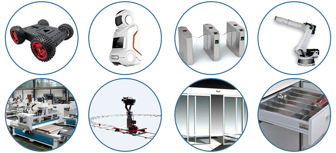
Application
Application scope: mechanical arms, passage turnstiles, intelligent trolleys, electric drawers, track pan-tilt units, automatic
doors, service robots, various types of automatic control, etc
Special functions
1.One-click motor phase sequence adaptation
The three-phase lines and three Hall signal lines of the motor do not need to be connected to the driver in sequence. Just one click operation is required to learn the Hall sequence of the motor.
After performing six commutation controls on the motor, the learning is completed and the motor can be driven normally.
2. Automatic acceleration and deceleration control for reciprocating motion
When controlling reciprocating motion, the driver can pre-learn the total stroke of the reciprocating motion (or directly configure the value), and automatically control the motor to move rapidly and smoothly to the target position in accordance with Newton's laws of motion based on the configured acceleration and deceleration acceleration and maximum speed.
3. The motor can be adjusted at any position within a fixed stroke
The driver can pre-learn the total stroke of the reciprocating motion (or directly configure the value), and then use a potentiometer, analog quantity or PWM to adjust the position of the motor within a fixed stroke. The motor position is linearly related to the input quantity. If the potentiometer is rotated to the midpoint and the input duty cycle is given at 50%, then the motor will move to the midpoint of the stroke.
4. Brushless motors can also be steplessly controlled
Select the input signal as PWM/ frequency/pulse, configure the pulse type as pulse, and set the working mode as position control. Then, the brushless motor can be operated like a stepper motor. One pulse signal can control the motor's rotation Angle, and another pulse signal can control the rotation direction. The rotation Angle of the motor corresponding to each pulse can be configured.
5.Brushless motors can also be servo-controlled
Under the 485 communication control mode, the target position (absolute position or relative to the current position) can be directly given to rotate the driver to the target position. The driver will automatically control the motor to move rapidly and smoothly to the target position in accordance with Newton's laws of motion based on the set acceleration and deceleration acceleration and maximum speed. During the movement process, the driver can predict the remaining time required to complete the task.
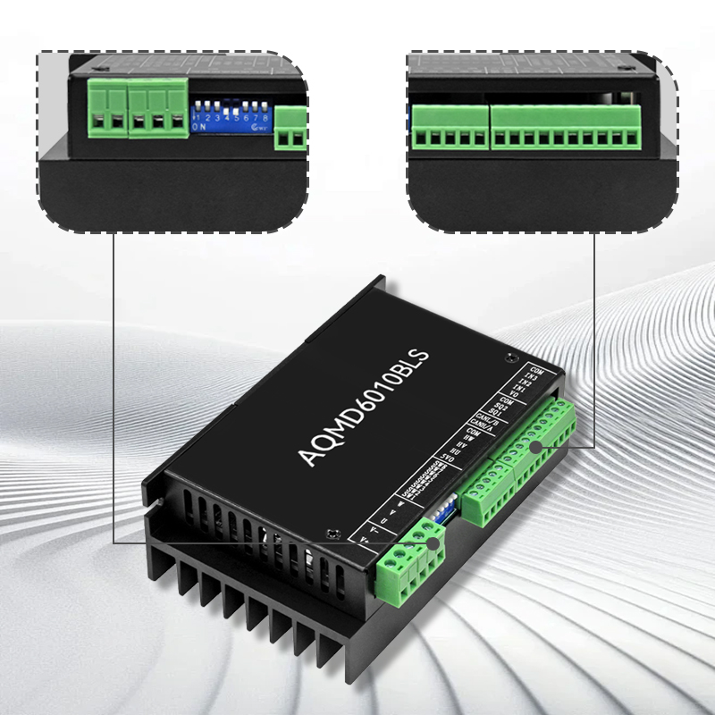
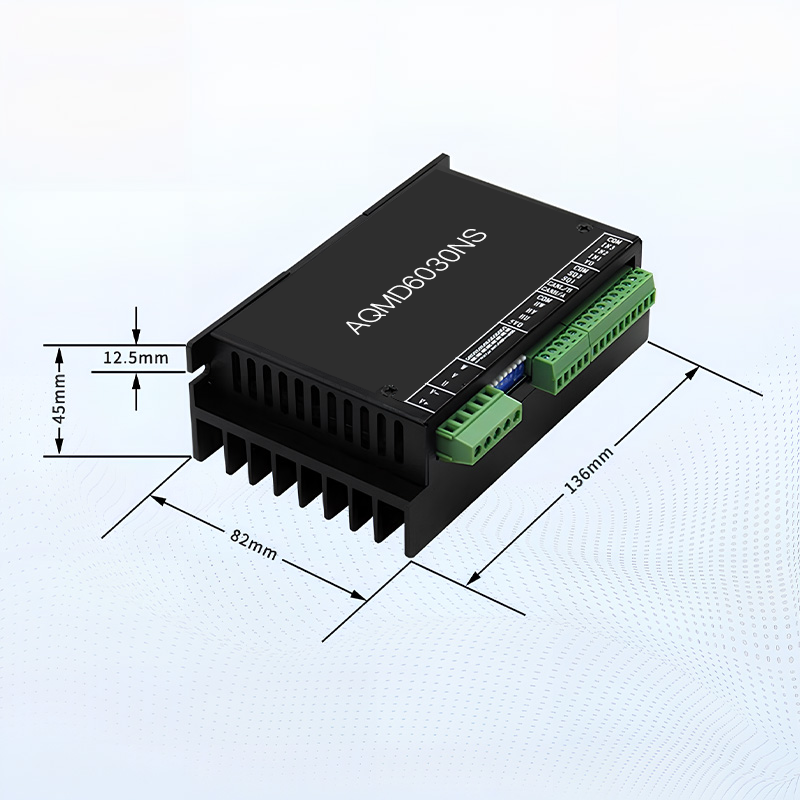
Dimensional drawing
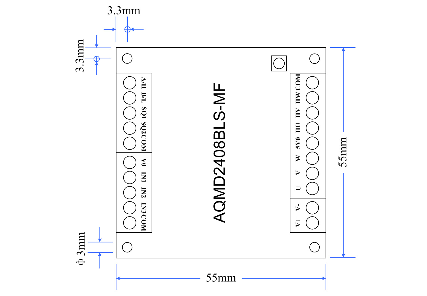
The size definition of AQMD2408BLS-M: The size of the driver is 5.5mm x 5.5mm x 1.7mm, the diameter of the installation hole is 3mm, and the distance from the center of the installation hole to the side is 3.4mm.
Product parameters
Note: This driver is suitable for DC inductive brushless motors.
Comparison project |
9-24V rated 8A |
9-24V rated 3A |
9-24V rated 8A communication isolation /FOC |
Support control signals | Potentiometer, 0-3.3V analog quantity, PWM, frequency, pulse, level, switch quantity, 485 communication control | Potentiometer, 0-3.3V analog quantity, PWM, frequency, pulse, level, switch quantity, 485 communication control | Potentiometer, 0-3.3V analog quantity, PWM, frequency, pulse, level, switch quantity, 485/CAN communication control |
Support voltage | 9-24V | 9-24V | 9-24V |
Rated output current | 8A | 3A | 8A |
Maximum output current | 16A(double current)/10A(non-double current) | 6A(double current)/4A(Non-double current) | 16A(double current)/10A(non-double current) |
Braking mode | Energy consumption braking/energy feedback | Energy consumption braking | Energy consumption braking/energy feedback |
Maximum soft braking current | 3A | 3A | 3A |
Maximum compatible motor | 24V-130W 12V-45W | 24V-50W 12V-18W | 24V-130W 12V-45W |
Size | 5.5 × 5.5 * 7 cm | 4.5 * 4.5 * 1.7 cm | 5.5×5.5×1.7cm |
Feature | Compact size, large current | Extremely small size | Communication isolation, compact size, large current |
Note: This driver is suitable for DC inductive brushless motors. The AQMD2408BLS-M/Me/MF can frequently change direction with a large current only when using the battery-powered energy feedback braking mode. AQMD2403BLS-M cannot frequently commutate at large currents. The rated power marked on a motor generally refers to the output power. Considering the working loss of the motor, the motor efficiency should be taken into account when calculating the rated current. Rated current = rated power/Rated voltage/efficiency. | |||
Main electrical parameters
Project | Parameters |
Power input voltage | DC9V~24V |
Rated output current | 8A; 3A |
Maximum output current | Rated 8A model: 10A(non-double current)/16A(double current output) |
Hall sensor interface voltage | Rated 3A model: 4A(non-double current)/6A(double current output): |
Maximum soft braking current | 5V |
Number of output channels | 3A |
Potentiometer resistance value | Single path |
The voltage range accepted by the input signal port | 10K~50K |
Analog signal range | 0 ~ 25V(except for the faulty/completed signal output port) |
Digital signal voltage range | Any within the range of 0 to 3.3V |
The PWM input signal supports a frequency range | Any within the range of 0 to 5V, such as LvTTL,TTL,HVTTL, etc |
Frequency input signal support range | 0~10kHz |
Output PWM frequency | 18kHz |
Output PWM resolution | 1/1000 |
RS485 communication parameter range | The baud rate ranges from 9600 to 115200bps, with 8 data bits. It supports odd, even, and no parity, and the parity bit and stop bit total 2 bits |
Support for Modbus | Supports Modbus-RTU, supports 03H, 06H, and 10H function codes, configurable slave station address range 1 to 128, and supports broadcasting |
Current detection resolution | Model 3A 0.04A; Model 8A: 0.02A |
Constant flow control accuracy | 0.04A |
Duty cycle speed regulation range | 0~100.0% |
Stable speed control adjustment range | -3276.8~3276.7Hz |
Position control adjustment range | -2147483648~2147483647 |
Torque control adjustment range | 0 to rated current |
Limit control | Support: Two external limit switches can be connected for limit or locked rotor time limit |
Soft start/soft braking | Support: Current-limited start, braking, and setting of acceleration and deceleration time as well as acceleration |
Overcurrent/locked rotor protection | Support; Overcurrent time-limited output: The machine can be shut down when there is a locked rotor |
Output short-circuit protection | Configurable |
Braking action time | Soft braking usually takes 0.1 seconds to 0.3 seconds |
Operating temperature of the motherboard | -25℃~85℃ |
External dimensions | 24V rated 3A model: 4.5cm×4.5cm×1.7cm |
Principle Introduction:
This driver employs leading motor current precise detection technology, self-speed measurement for inductive brushless motors, detection of the rotation position of inductive brushless motors, regenerative current constant current braking (or braking) technology, and powerful PID regulation technology to perfectly control the smooth forward and reverse rotation, reversing, and braking of the motor. The output current is regulated in real time to prevent overcurrent, and the motor speed and rotation position are precisely controlled. The motor has a short response time and a small recoil force.
1. Motor acceleration and deceleration control: The soft start mode with automatic current regulation and automatic acceleration control enables the motor to start quickly and smoothly with small recoback force. It supports the configuration of acceleration and deceleration time and acceleration.
2. Motor braking control: Energy consumption braking method with automatic current regulation, short motor braking time without strong shock and vibration. Support braking current configuration.
3. Motor commutation control: The process of switching between forward and reverse rotation of the motor is internally controlled by the driver, which automatically performs deceleration, soft braking, and soft start control. No matter how frequently the commutation signal changes, it will not cause damage to the driver or the motor.
4. Motor speed stabilization control: The rotational speed and rotation position are detected through Hall signals, and closed-loop control is carried out using the PID regulation algorithm. It supports two speed stabilization methods: speed closed-loop control and time-position closed-loop control.
5. Motor position control: The rotation position is detected through Hall signals, and position closed-loop control is carried out using PID regulation algorithms. Deceleration is achieved through brake resistors.
6. Motor torque control: The control of motor torque is achieved by adjusting the magnitude of the output current.
7. Motor overload and locked-rotor protection: When the motor is overloaded, the driver will limit the current output, effectively protecting the motor. When the motor is locked, the driver can detect this state and brake the motor.
8. Internal interference suppression: The drive circuit and the control circuit are coupled through interference consumption and transient interference suppression methods, which can effectively ensure that the control circuit is not affected by the interference from the drive circuit.
9. External interference suppression: ESD protection devices and electrostatic discharge circuits are used to provide ESD protection for all interfaces, ensuring the stable operation of internal circuits and protecting internal components from being damaged by transient high-voltage electrostatic shock applied to the interfaces.
Key usage
Operation mode | Function | Explanation | Status indicator light |
Press briefly | Motor phase sequence learning | Learn to succeed | After the yellow light and the green light flash alternately six times, they remain constantly on simultaneously for 1 second |
Learning failure | After the yellow light and the green light flash alternately for six times, the yellow light flashes continuously for three more times | ||
Hold for 1 second and then release | Switch control mode | Digital/analog signal control | The yellow light is always off and the green light flashes at a frequency of 0.5/2Hz |
485 Communication control | The yellow light remains on constantly and the green light flashes at a frequency of 0.5/2Hz | ||
Press and hold for 5 seconds and then release | Default communication parameters for communication | The baud rate is 9600bps, the check method is even check, and there is 1 stop bit |
Typical usage
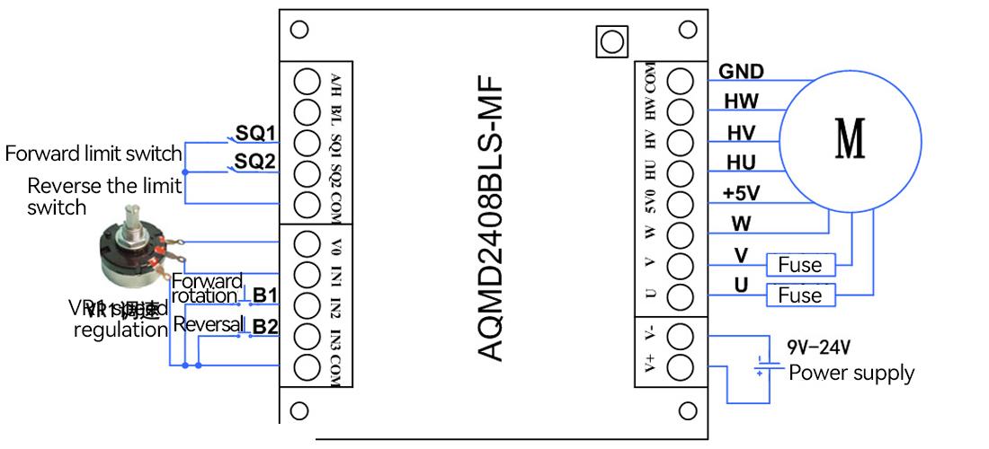
1.The connection method of single potentiometer duty cycle/closed-loop speed regulation point control
Key Settings | ||
Control mode | Indicator light status | |
Digital/analog signal control mode | The yellow light is always off, while the green light is always on or flashing | |
Register configuration | ||
Register address | value | Description |
0X009a | 1 | Potentiometer |
0X009b | 1 | Duty cycle speed regulation |
3 | Speed closed-loop control | |
0X0080 | 0 | Low-level limit (default) |
0X0081 | 0 | Low level effective (default) |
0X0082 | 0 | Single potentiometer (default) |
0X0085 | 0 | Switch quantity (default) |
The working process of the point control mode using potentiometer speed regulation is as follows: Press B1, the motor rotates forward, and the speed regulation is carried out using the potentiometer. B1 bounces up and the motor stops. When the motor stops after the forward rotation limit, pressing B1 again is ineffective. Press B2 to reverse the motor. Use the potentiometer to adjust the speed. B2 bounces up and the motor stops. When the reverse limit is applied, the motor stops. Pressing B2 again is ineffective.
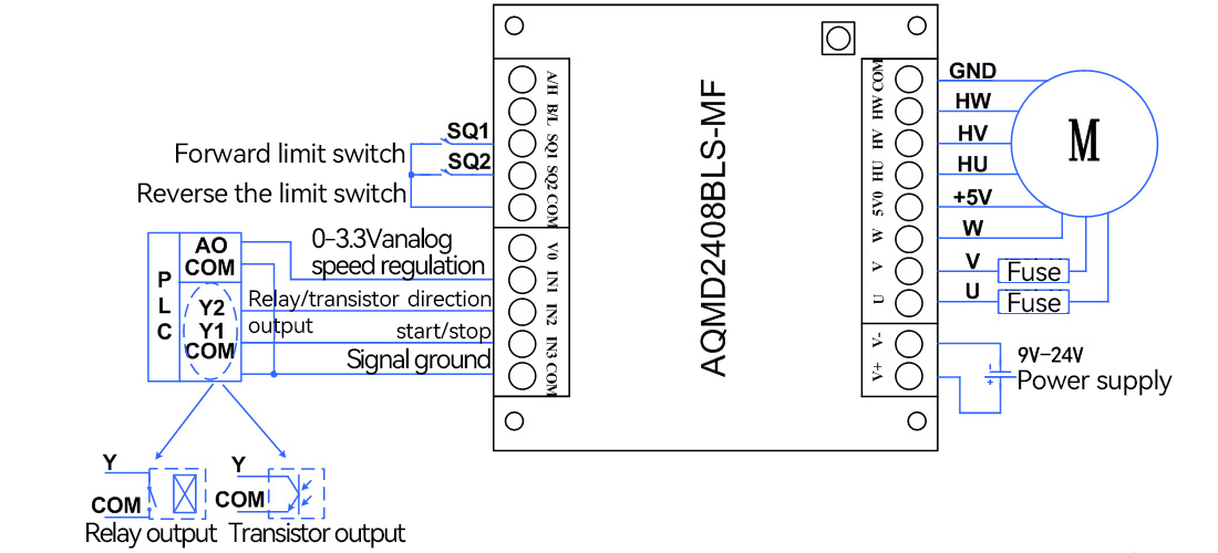
2. The connection method of duty cycle/closed-loop speed regulation of PLC analog signals
Key Settings | ||
Control mode | Indicator light | |
Digital/analog signalControl mode | The yellow light is always off, while the green light is always on or flashing | |
Register configuration | ||
Register address | value | Description |
0X009a | 2 | Analog signal |
0X009b | 1 | Duty cycle speed regulation |
3 | Speed closed-loop control | |
0X0080 | 0 | Low-level limit (default) |
0X0081 | 0 | Low level effective (default) |
0X0084 | 0 | Single-ended signal (default) |
0X0085 | 0 | Switch quantity (default) |
0X0088 | 0 | 0mV |
0X0089 | 0X0CE4 | 3300mV |
The working process of this connection method is as follows: IN1 is connected to the AO port of the PLC for speed regulation; IN2 is connected to Y2 of the PLC to control the direction of the motor. IN3 is connected to Y1 of the PLC to control the emergency stop of the motor.
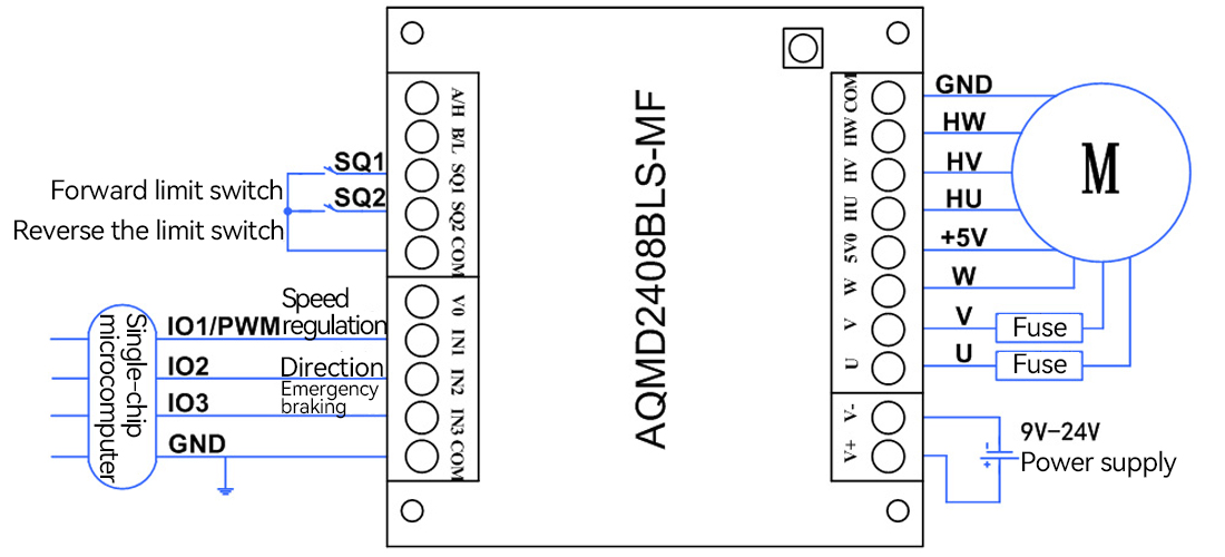
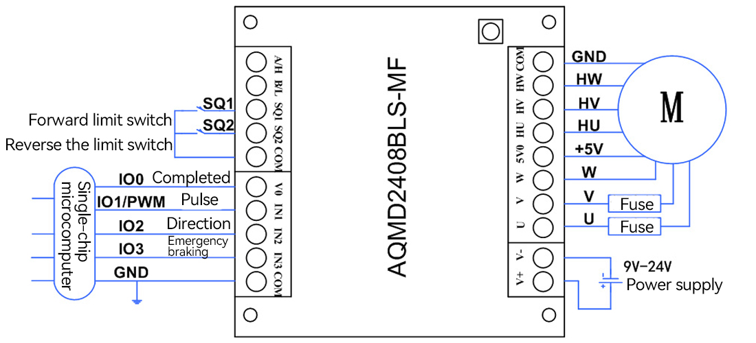
3. The connection method of duty cycle/closed-loop speed regulation of the PWM signal of the single-chip microcomputer
Key Settings | ||
Control mode | Indicator light | |
Digital/analog signalControl mode | The yellow light is always off, while the green light is always on or flashing | |
Register configuration | ||
Register address | value | Description |
0X009a | 3 | Pulse signal |
0X009b | 1 | Duty cycle speed regulation |
3 | Speed closed-loop control | |
0X0080 | 0 | Low-level limit (default) |
0X0081 | 0 | Low level effective (default) |
0X0083 | 0 | PWM(default) |
0X0085 | 1 | 0/3.3V |
2 | 0/5V | |
The working process of this connection method is as follows: The power supply of the single-chip microcomputer is grounded to the COM port of the drive module. Pin IN1 is connected to the PWM output of the single-chip microcomputer for speed regulation. IN2 and IN3 are connected to the two IOs of the single-chip microcomputer to control the forward and reverse rotation of the motor and emergency braking.
4. Connection method of pulse signal position control for single-chip microcomputer
Key Settings | ||
Control mode | Indicator light | |
Digital/analog signalControl mode | |The yellow light is always off, while the green light is always on or flashing | |
Register configuration | ||
Register address | value | Description |
0X009a | 3 | Pulse signal |
0X009b | 4 | Position closed-loop control |
0X0080 | 0 | Low-level limit (default) |
0X0081 | 0 | Low level effective (default) |
0X0083 | 2 | Pulse |
The working process of this connection method is as follows: The power supply of the single-chip microcomputer is grounded to the COM port of the drive module. IN1 is connected to IO1 of the single-chip microcomputer to determine the number of pulses, which is used for motor position control. VO is connected to IO0 of the single-chip microcomputer and is used to complete signal control. IN2 and IN3 are connected to the two IOs of the single-chip microcomputer to control the forward and reverse rotation of the motor and emergency braking.
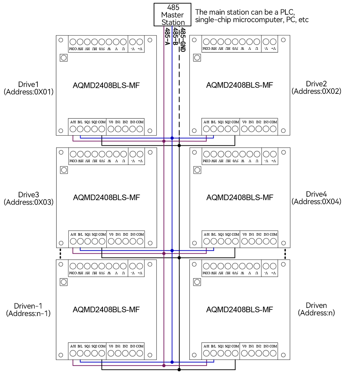
5. Connection method for 485 multi-site control
Key Settings | |
Control mode | Indicator light |
485 Communication control | The yellow light is always off, while the green light is always on or flashing |
Communication parameter configuration register | |
Register address | Description |
0X009c | Slave station address |
0X0090-0X0091 | Baud rate |
0X0092 | Verification method |
Configuration of registers related to motor control | |
Register address | Description |
0X0040 | Motor braking control |
0X0042 | Set the duty cycle |
0X0043 | Set the target speed for the speed closed-loop control |
0X0044 | Set the position for closed-loop control of the walking speed |
0X0045 | Set the type of position closed-loop control |
0X0046-0X0047 | Set the position for closed-loop control of the target position |
The 485 communication lines of each driver are connected in parallel in the form of A-A and B-B and then linked to A 485 master station. The 485 master station operates each driver independently through the slave station address configured by the driver. The address configured for each drive should be different and cannot be duplicated with other drives.
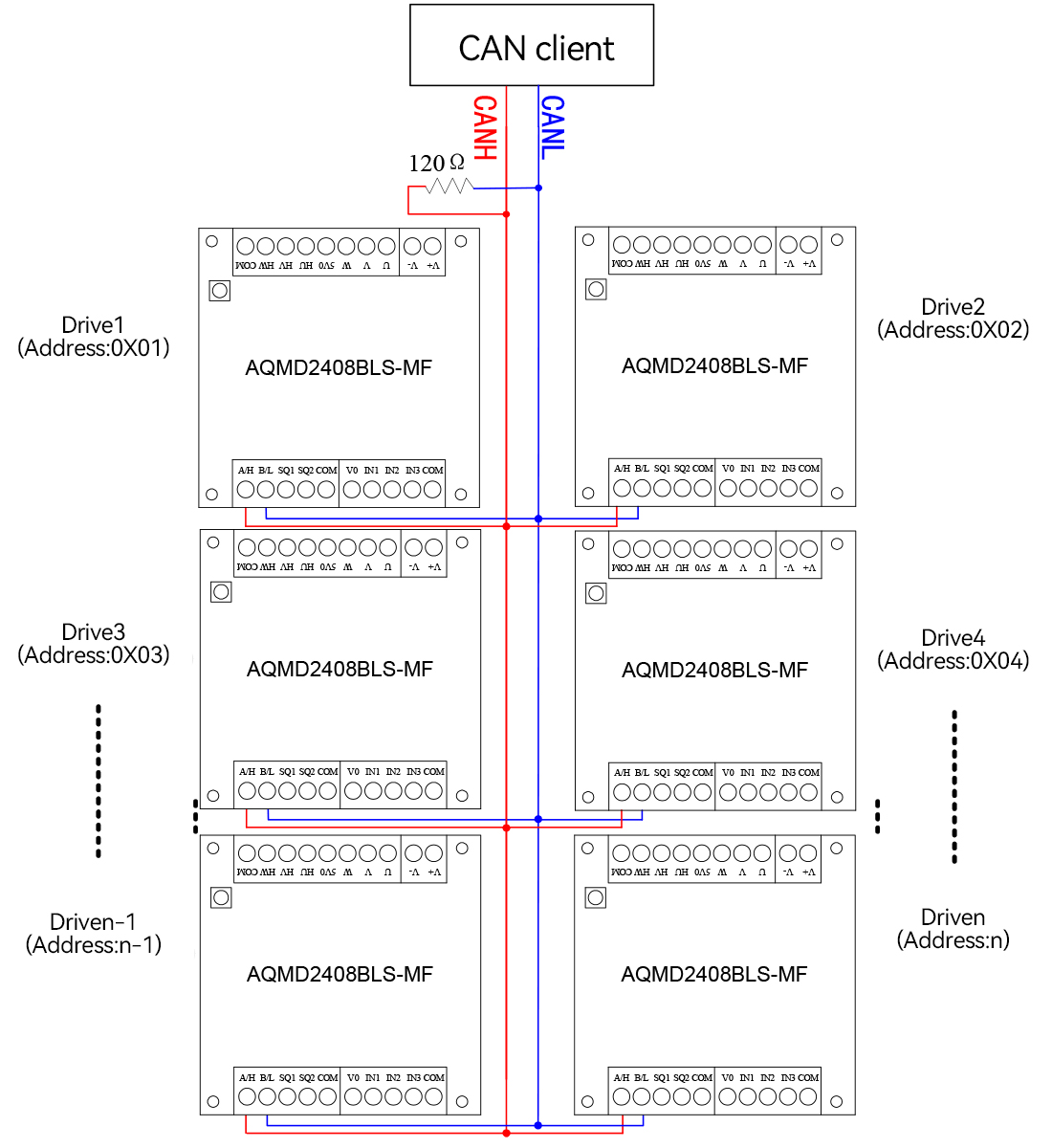
6. Connection method of CAN multi-node control
Key Settings | |
Control mode | Indicator light |
CAN communication control | The yellow light is always off, while the green light is always on or flashing |
Communication parameter configuration register | |
Register address | Description |
0X0120 | CAN communication mode |
0X0121 | CAN node ID |
0X0122 | CANBaud rate |
Configuration of registers related to motor control | |
Register address | Description |
0X2000 | Motor control type |
0X2001 | Motor control quantity |
0X2002 | Location type |
0X2003 | Target location |
The CAN communication lines of each driver are connected in parallel in the form of CANH-CANH and CANL-CANL and then connected to the CAN client. At least one 120Ω resistor is connected in parallel on the CAN bus. The CAN client operates each driver independently through the node ID configured on the driver. The node ID configured for each drive should be different and cannot be duplicated with that of other drives.
Sample program
Provide a PC sample program, which can be used for parameter configuration, motor debugging or secondary development.
Appendix: Selection reference
Selection Table for AQMD_BLS Series DC Inductive Brushless Motor Drivers
Model number | Functional characteristics | Maximum fit | Maximum current / | Energy braking | Control signal | Product size |
AQMD2403BLS-M | ● Minimal size | 12V18W | 6A/3A | 3A, do not brake frequently with high current | Single/dual potentiometer, 0-3.3V analog signal, logic level, switch, key, PWM, pulse, frequency, RS485 | 45x45x18mm bare board |
AQMD3605BLS-B2 | ● Overheat protection | 12V-30W | 10A/5A | 3A, do not brake frequently with high current | Single/dual potentiometer, 0-3.3V analog signal, logic level, switch, key, PWM, pulse/frequency, RS485 | 70x65x2lmm Raw board |
AQMD2408BLS-M | ● Compact size | 12V-45W | 16A/8A | 3A, non-battery power can not be high current frequent brake reversing | Single/dual potentiometer, 0-3.3V analog signal, logic level, switch, key, PWM, pulse/frequency, RS485 | 55x55x17mm bare board |
AQMD3608BLS | ● Rail mounting | 12V-50W | 10A/8A | 3A, do not brake frequently with high current | Single/dual potentiometer, 0-3.3/5/10V analog signal, logic level, switch, key, PWM, pulse/frequency, RS485 | 92x87x30mm bare plate |
AQMD6008BLS-T | ● Compact case | 12V-50W | 16A/8A | 3A | Single/dual potentiometer, 0-3.3V analog signal, logic level, switch, key, PWM, pulse/frequency, RS485 | 93x56x20.5mm |
AOMD6008BLS-TE/-I | Single/dual potentiometer, 0-3.3/5/10V analog signal, logic level, switch, key, PWM/ pulse/frequency, RS485/CAN | |||||
AOMMD6008BLS-TF/-I | ||||||
AQMD6010BLS-B2 | ● Overheat protection | 12V-60W | 20A/10A | 6A | Single/dual potentiometer, 0-3.3/5/10V analog signal, logic level, switch, key, PWM/ pulse/frequency, RS485 | 136x82x45mm |
AOMD6010BLS-E2 |
| 20A/10A | 6A | Single/dual potentiometer, 0-3.3/5/10V analog signal, logic level, switch, key, PWM/ pulse/frequency, RS485/CAN | 136x82x45mm | |
AOMD6010BLS-E2F | 8A | |||||
AQMD6020BLS-E2/E3 |
| 12V-100W | 35A/16A | 6A | Single/dual potentiometer, 0-3.3/5/10V analog signal, logic level, switch, key, PWM/ pulse/frequency, RS485/CAN | 136x82x45mm |
AOMD6020BLS-E2F | 8A | |||||
AQMD6030BLS-E2/E3 |
| 12V-180W | 40A/25A | 12A | Single/dual potentiometer, 0-3.3/5/10V analog signal, logic level, switch, key, PWM/ pulse/frequency, RS485/CAN | 136x82x45mm |
AQMD6030BLS-E2F | ||||||
AOMD6040BLS-E2 |
| 12V-240W | 50A/35A | 20A | Single/dual potentiometer, 0-3.3/5/10V analog signal, 0-3.3/5/24V logic level, switch, key, PWM, pulse, frequency, RS485/CAN communication | 178x108x68mm |
AQMD6040BLS-E2F | ||||||
AQMD12H10BLS-E2 | ● Overheat protection | 24V-200W | 25A/12A | 6A | Single/dual potentiometer, 0-3.3/5/10V analog signal, logic level, switch, key, PWM/ pulse/frequency, RS485/CAN | 136x82x45mm |
AOMD12H30BLS-E2 | ● Overheat protection | 24V-500W | 45A/30A | 12A | Single/dual potentiometer, 0-3.3/5/10V analog signal, logic level, switch, key, PWM/ pulse/frequency, RS485/CAN | 178x108x68m1 |
AQMD22A04BLS-E2 | ● Overheat protection | 72V-175W | 7A/3.5A | 3A | Single/dual potentiometer, 0-3.3/5/10V analog signal, logic level, switch, key, PWM/ pulse/frequency, RS485/CAN | 136x82x45mm |
Product protection
Multiple protections ensure safety and reliability

Overcurrent protection | Locked rotor protection | Voltage monitoring | Temperature monitoring | Communication isolation | Abnormal current protection |
After-sale guarantee
After-sales service: We offer comprehensive after-sales technical support. If you encounter any problems during use, our professional after-sales engineer team will respond promptly and provide you with detailed solutions through phone calls, emails or remote assistance. We also offer regular follow-up visits to our products to understand their usage and collect your feedback, so as to continuously optimize our products and services. In addition, we strictly adhere to the warranty policy. For products with quality issues within the warranty period, we offer free repair or replacement services to ensure you have no worries.