
Product Description
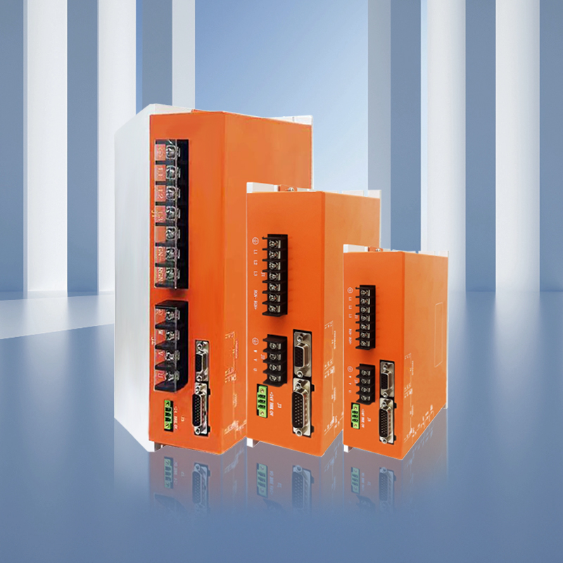
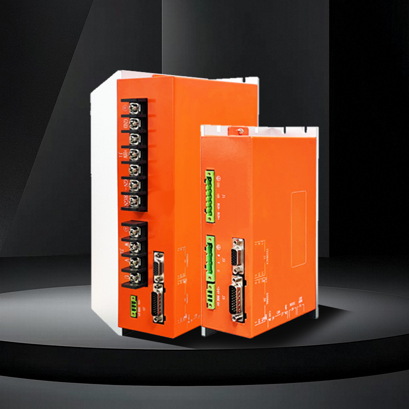
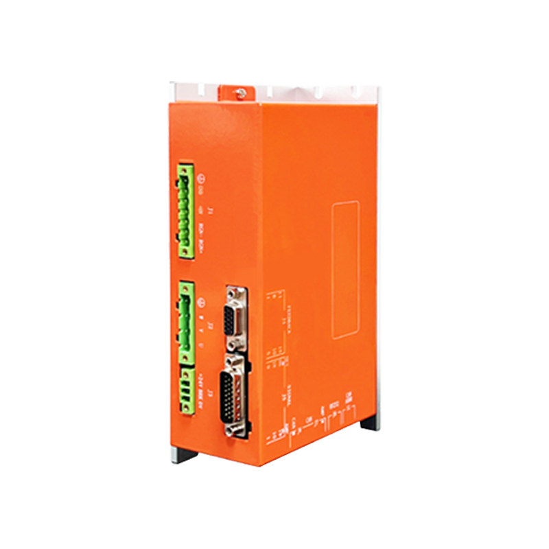
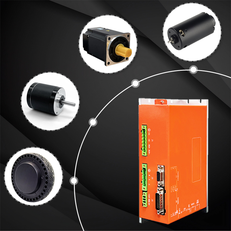
BL series servo driver
Fast
Intelligent
Accurate
The BL series programmable intelligent servo driver is a universal, high-performance, AC/DC powered, compact, all-digital servo driver. It is mainly applied to the position, speed and torque control of brushless servo motors. It supports incremental encoders, resolvers, absolute encoders, Tama River protocol, and digital Hall feedback.
Functional Features
Technical characteristics | ||
◆ Control mode: Position, speed, torque; | ||
Input voltage | 110-240 AC | One-phase ,Three-phase |
Input frequency | 47-63Hz | / |
Electrical standard specifications | ||||
Position control | Instruction control mode | Pulse, ±10V analog input, CANopen, RS485 MODBUS RTU | ||
Input signal | Pulse instruction | Input pulse pattern | It includes three instruction forms: "direction + pulse", "A and B phase orthogonal pulse", and "CW/CCW pulse". | |
Signal format | Collector open circuit | |||
Maximum pulse frequency | Collector open circuit :(Maximum 500Kpps) | |||
Simulation instruction | Voltage range | Input voltage range ±10V | ||
Input impedance | Differential input impedance =5KΩ | |||
Speed control | Instruction control mode | PWM, ±10V analog quantity, pulse, CANopen, RS485 MODBUS RTU | ||
Input signal | PWM | Polarity | PWM=0-100%, polarity =1/0 | |
Non-polarity | PWM= 50% +/-50% | |||
Frequency range | Minimum 1kHz, maximum 100kHz | |||
Minimum pulse width | 220ns | |||
Simulation instruction | Voltage range | Input voltage range ±10V | ||
Input impedance | Differential input impedance =5KΩ | |||
Current control | Instruction control mode | PWM, ±10V analog quantity, CANopen, RS485 MODBUS RTU | ||
Input signal | PWM | Polarity | PWM=0-100%, polarity =1/0 | |
Non-polarity | PWM= 50% +/-50% | |||
Frequency range | Minimum 1kHz, maximum 100kHz | |||
Minimum pulse width | 220ns | |||
Simulation instruction | Voltage range | Input voltage range ±10V | ||
Input impedance | Differential input impedance =5KΩ | |||
I/O signal | Digital input IN | The number of ports | 12(Among them, IN6, IN7, IN8, IN9 and IN10 are high-speed ports, and IN5 is internally used for motor temperature protection) | |
Signal format | NPN(Effective at low level) | |||
Settable functions | Servo enable, external reset, forward/reverse limit, motor operation stop, high-speed pulse input, etc | |||
Digital output OUT | The number of ports | 3 | ||
Signal format | NPN(effective at low level), capable of withstands a maximum current of 300 madC and a maximum voltage of 30Vdc | |||
Settable functions | Fault signal, brake control, custom event trajectory status | |||
Function | LED indication | Driver status indication, communication indication | ||
Communication function | RS-232 | Baud rate | 9600-115200. | |
Agreement | Full-duplex mode, ASCII or binary format | |||
RS485 | Baud rate | 9600-115200 | ||
Agreement | MODBUS RTU | |||
CAN | Baud rate | 20kbit/s-1Mbit/s | ||
Agreement | Canopen Application Layer DS-301V4.02 | |||
Equipment | DSP-402 device drive and motion control | |||
Protection function | Overvoltage, overcurrent, undervoltage, overload, overheating, encoder abnormality, excessive position tracking error and other protections | |||
Usage environment | Installation location | No corrosive gases, flammable gases, etc | ||
Installation location | Less than 1,000 meters | |||
Temperature | 0°C~+50°C | |||
Humidity | 5% to 95%RH, no water droplets condense | |||
Vibration resistance/shock resistance strength | Less than4.9m/s2/Less than19.6m/s2 | |||
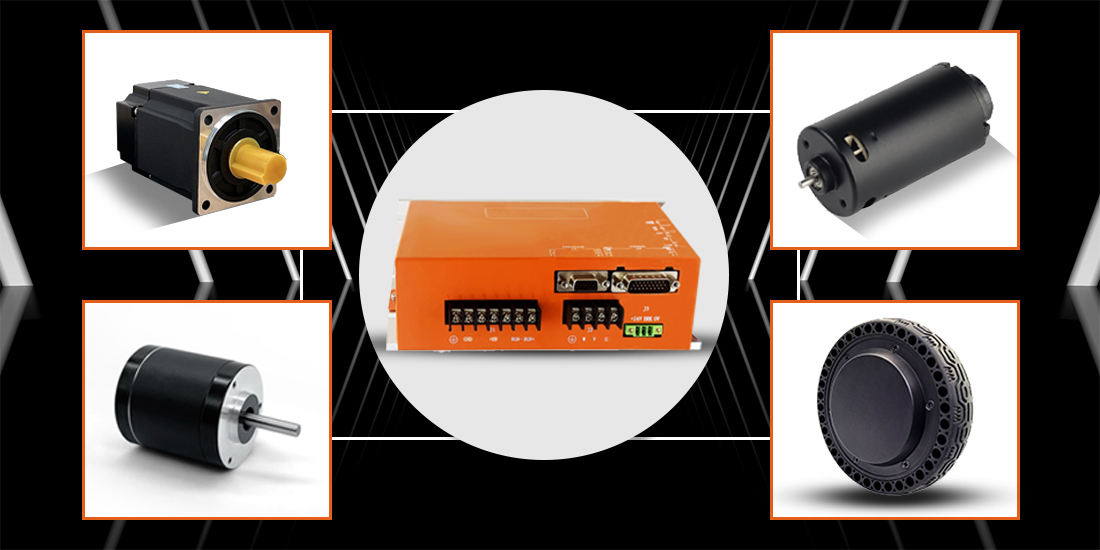
Application
Servo drivers are applied in various servo motors, brushless motors, robot fields, new energy fields, automation fields, AGV automotive industries, and control systems. They can convert input voltage signals into mechanical output quantities on the motor shaft, drive the controlled components, and thereby achieve the control purpose.
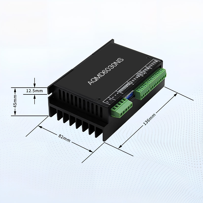
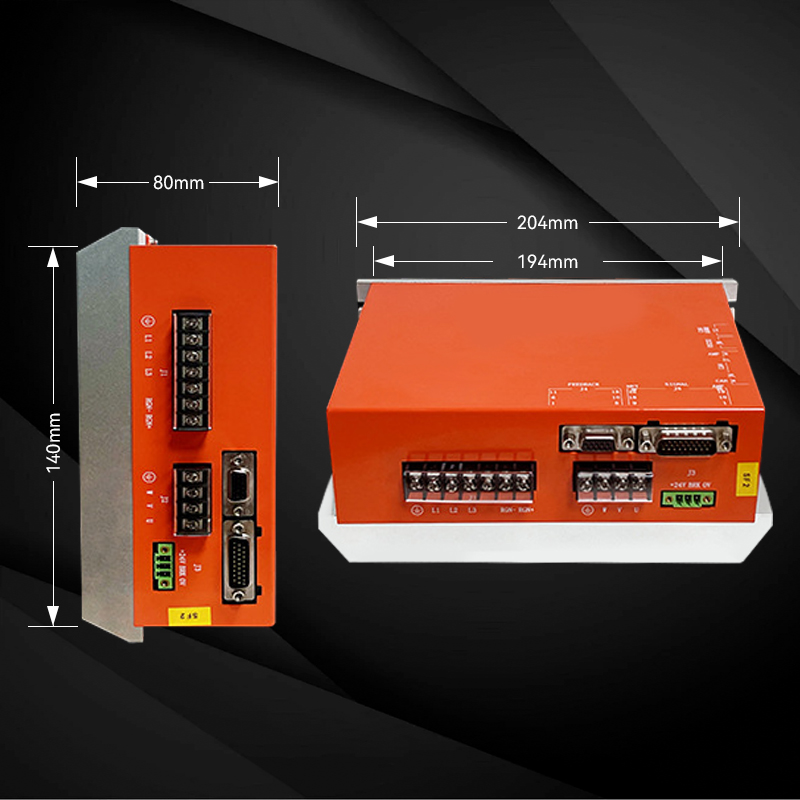
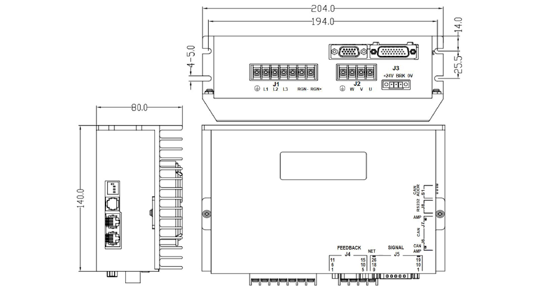
Dimensional drawing
BL series external dimensions drawing:
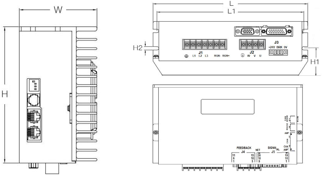
Model | L | L1 | W | H | H1 | H2 |
BLPC/R-220B03-OPE/AB | 194 | 174 | 58.5 | 113.5 | 21 | 4-5.0 |
BLPC/R-220B07-OPE/AB | ||||||
BLPC/R-220B10-OPE/AB | 204 | 194 | 60 | 140 | 21 | 4-5.0 |
BLPC/R-220B14-OPE/AB | 204 | 194 | 80 | 140 | 40.5 | 4-5.0 |
BLPC/R-220B17-OPE/AB | ||||||
BLPC/R-220B25-OPE/AB | 285 | 275 | 188 | 114 | 20.5 | 4-5.0 |
BLPC/R-220B35-OPE/AB |
Model Description
BL | PC | -220B | 15 | -OP | E | B | GT | ||||||||||||||
Series | |||||||||||||||||||||
BL/DH/LS/BH | Special requirements | ||||||||||||||||||||
GT: Green terminal version | |||||||||||||||||||||
Input instructions | |||||||||||||||||||||
P:Pulse A:Analog quantity R:RS485 C:CANopen | Braking unit | ||||||||||||||||||||
B: With a braking unit | |||||||||||||||||||||
Power supply voltage | |||||||||||||||||||||
220:220VAC 380:1380VAC B:Three-phase | Feedback | ||||||||||||||||||||
E: Incremental A/B orthogonality | |||||||||||||||||||||
A: Absolute value (Tama River RS485) | |||||||||||||||||||||
Rated current | |||||||||||||||||||||
03:3.5Arms 07:7Arms 10:10Arms | Special function | ||||||||||||||||||||
17:17Arms 25:25Arms 35:35Arms | OP: Pulse output | ||||||||||||||||||||
Product parameters
Summary table of Driver Specifications | ||||||
Driver model | Power supply voltage | Amps(Arms) | Amps(Arms)6S | Feedback type | External dimensions | Weight |
BLPC/R-220B03-OPE/AB | 220VDC | 3.5A | 10.5A | Incremental or absolute | 194*113.5*58mm | 0.9kg |
BLPC/R-220B07-OPE/AB | 7A | 14A | ||||
BLPC/R-220B10-OPE/AB | 10A | 26.5A | 204*140*60mm | 1.2kg | ||
BLPC/R-220B14-OPE/AB | 14A | 42A | 204*140*80mm | 1.2kg | ||
BLPC/R-220B17-OPE/AB | 17A | 44A | ||||
BLPC/R-220B25-OPE/AB | 24.5A | 73.5A | 285*188*114mm | 3.8kg | ||
BLPC/R-220B35-OPE/AB | 35A | 84A | ||||
Note: 1. The supply voltage of the driver must be greater than or equal to the rated voltage of the motor; | ||||||
Application wiring diagram
BL series system wiring diagram:
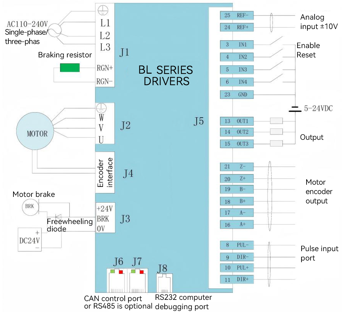
Explanation:
1. The input terminals IN1, IN2, IN3, IN4, IN5, IN11, and IN12 are common ports that can receive NP N and P NP signals, with a maximum input voltage of 24V
2. IN6, IN7, IN8, IN9, and IN10 are high-speed input ports with a maximum input voltage of 5V
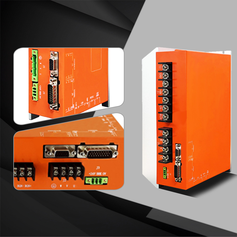
BL series terminal definition
Definition of connection port | ||
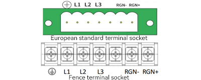
1、Three-phase input terminal J1 of the main power supply | ||
| L1 | AC220V |
L2 | ||
L3 | ||
 | to | |
RGN- | Braking resistor interface | |
RGN+ | ||
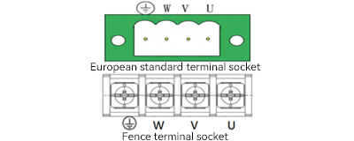
2、Motor interface J2 | ||
| U | Motor wire U |
V | Motor wire V | |
W | Motor wire W | |
 | Motor wire PE | |
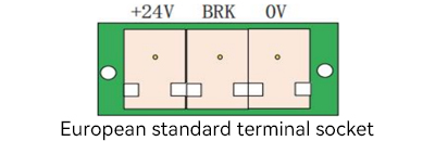
3、Internal 24v output terminal J3 | ||
| +24V | 24v output 200mA |
BRK | Connect the motor brake wire | |
0V | 0V | |
4、Motor encoder input terminal J4 | |||||
| |||||
Pin | Definition | Function | Pin | Definition | Function |
1 | A+ | Motor encoder A+ input | 9 | V+ | Motor encoder V+ input |
2 | A- | Motor encoder A- input | 10 | COS* | NTC1/ Temperature Switch 1 |
3 | B+(DAT+) | Motor encoder B+ input | 11 | W+ | Motor encoder W+ input |
4 | B-(DAT-) | Motor encoder B input | 12 | IN5* | Temperature switch 2 |
5 | Z+ | Motor encoder Z+ input | 13 | +5V | Motor signal line +5V |
6 | Z- | Motor encoder Z-input | 14 | 0V | Motor signal line GND |
7 | U+ | Motor encoder U+ input | 15 | NTC* | NTC2 |
8 | / | / | / | / | / |
Note: 1. * If you need the input function of the NTC resistance temperature sensor, connect to pin 10 and pin 15. Please specify when placing an order. | |||||

5、Control signal I/O terminal J5 | |||||
| |||||
Pin | Name | Function | Pin | Name | Function |
1 | FG | The Earth | 14 | OUT2 | Customize |
2 | IN5 | Motor temperature detection | 15 | OUT3 | Customize |
3 | IN1 | Enable | 16 | EONA+ | The motor encoder outputs the signal A+ |
4 | IN2 | Customize | 17 | EONA- | The motor encoder outputs signal A- |
5 | IN3 | Customize | 18 | EONB+ | The motor encoder outputs signal B+ |
6 | IN4 | Customize | 19 | EONB- | The motor encoder outputs signal B- |
7 | IN6 | Customize | 20 | EONZ+ | The motor encoder outputs the signal Z+ |
8 | IN7 | Customize | 21 | EONZ- | The output signal of the motor encoder is Z- |
9 | IN8 | Customize | 22 | +5V | 5V power output (400mA) |
10 | IN9 | Customize | 23 | GND | Power supply ground |
11 | IN10 | Customize | 24 | Ref+ | Positive input of analog quantity |
12 | IN11 | Customize | 25 | Ref- | Analog negative input |
13 | OUT1 | Customize | 26 | IN12 | Customize |

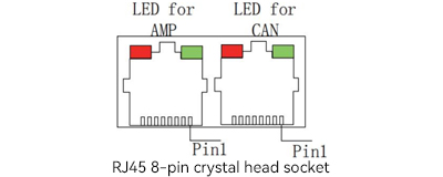
6、CAN(RS485)Communication terminals J6 & J7 | |||
This drive has two communication ports, which are defined as follows: | |||
| Pin | Definition | Name |
1 | CANH( RS485_A) | CANH signal (RS485_A) | |
2 | CANL(RS485_B) | CANL signal (RS485_B) | |
3/7 | GND | Communication power supply ground | |
Note: The two RJ45 ports in J6 and J7 have the same definition, which is convenient for bridging during communication. | |||
| ||
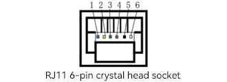
The 6P terminal block is defined as follows | ||
Pin | Definition | Name |
1 | CANH(RS485_A) | CANH signal (RS485_A) |
2 | CANH(RS485_A) | CANH signal (RS485_A) |
3 | C_GND | Communication power supply ground |
4 | C_GND | Communication power supply ground |
5 | CANL(RS485_B) | CANL signal (RS485_B) |
6 | CANL(RS485_B) | CANL signal (RS485_B) |

7、Driver status indicator Light (AMP | |
The red/green dual-color LED light tells us the status of the driver through color changes and whether it flashes or not. The possible situations are: | |
Green/Not flashing | The drive is OK and enabled |
Green/Slow flash | The drive is okay but not enabled. It can run after being enabled |
Green/Flash | When the positive or negative limit switch is effective, the motor will only move in the direction not prohibited by the limit switch |
Red/Fixed | Instantaneous fault. After the fault is eliminated, the amplifier needs to be restarted |
Red/Flashing | Lock the fault and restart the amplifier to resume operation |
8、Serial communication terminal J8 | |||
| Pin | Definition | Name |
2 | RXD | RS232 communication receiving terminal | |
3 | GND | Communication power supply ground | |
5 | TXD | RS232 communication sender | |
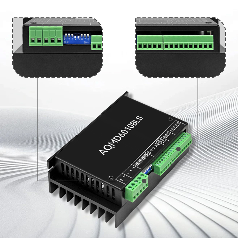
9、SW driver CAN address dip switch | |
When the software setting selection is to use an external dip switch, the dip of this switch is valid. The switch encoding follows the sequence of BCD codes. It is valid when the dial is set to ON | |
| |
The SW dip switch corresponds to the station number | |
SW Switch serial number | Corresponding station number |
1 | 1 |
2 | 2 |
3 | 4 |
4 | 8 |
For example, to set the station number to 3, switch 1 and 2 of the SW switch to ON and the others to off. 1+2=3. If you want to set the station number to 12, switch 3 and 4 of SW to ON, and set the rest to ooff. 4+8=12 | |

Service
Dedicated service, along the way
Warranty worry-free, extended repair, often return to promote optimization, peace of mind choice, all in control.

Online customer service Efficient logistics Deliver on time Quality Assurance Technical maintenance Manufacturer support
After-sale guarantee
After-sales service: We provide comprehensive after-sales technical support, if you encounter any problems in the process of use, the professional after-sales engineer team will respond quickly, through telephone, mail or remote assistance, to provide you with detailed solutions. We also provide regular return visits to our products to understand how they are used and to collect your feedback in order to continuously optimize our products and services. In addition, in strict accordance with the quality assurance policy, we provide free repair or replacement services for products with quality problems during the warranty period, so that you have no worries.