
Product Description
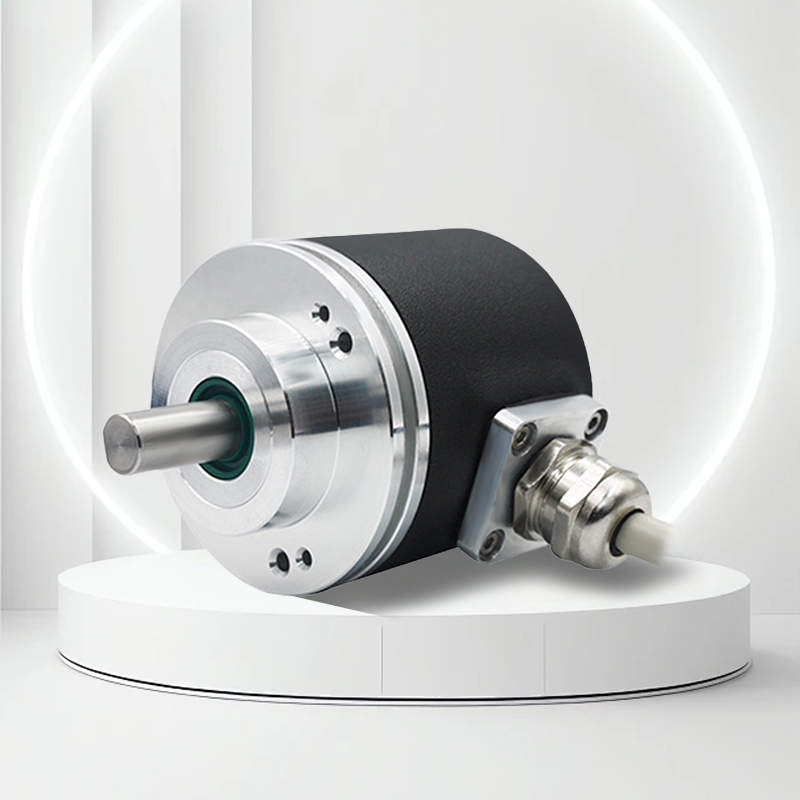
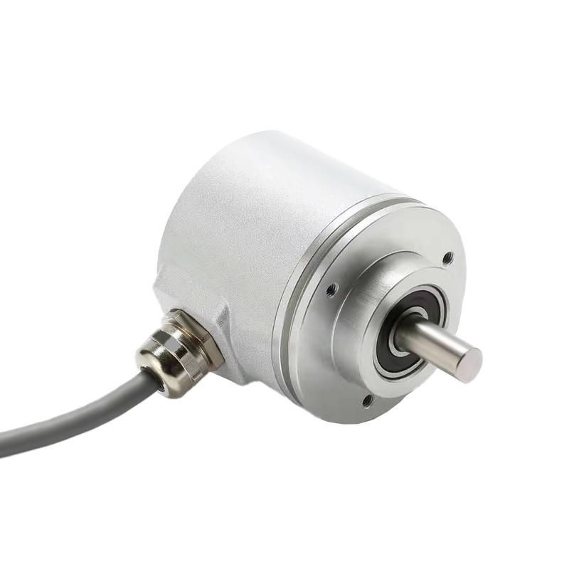
Programmable incremental encoder, supports RS485 interface to set the number of pulses arbitrarily, wide voltage and temperature range, shock and vibration resistance, multiple output modes, suitable for machine tools, robots and other automation scenarios.
Product Features | Performance optimization |
Note: The pulse number of this encoder has been set as required before leaving the factory. If you need to modify the pulse number during use, please indicate it when ordering. And ask the manufacturer for the modification operation method.
Product parameters
Mechanical parameters | Electrical parameters | ||
Maximum speed | 6000 rpm | Operating voltage | 4.75-30VDC |
Spindle load | Axial 40N, radial 100N | Consumption current | < 50mA (24Vdc) no load |
Impact resistance | 1000m/s²(6ms), equal to 100g | Output signal | PPR (1-16384) push-pull (HTL) TTL, open collector |
Vibration resistance | 200m/s²(10-2000Hz), equal to 20g | Rectangular deviation | 90°±4.5° |
Axial movement allowed | ±1.5mm | Response frequency | 1MHz |
Radial runout allowed | ±0.2mm | Consumption current | 40mA per channel |
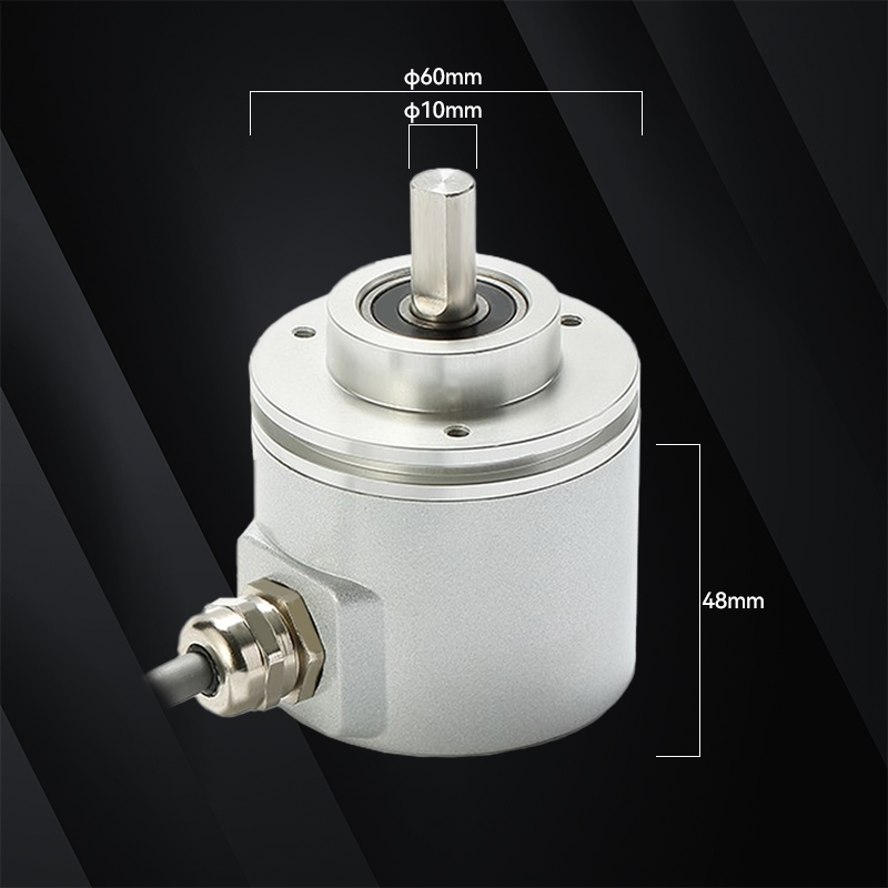
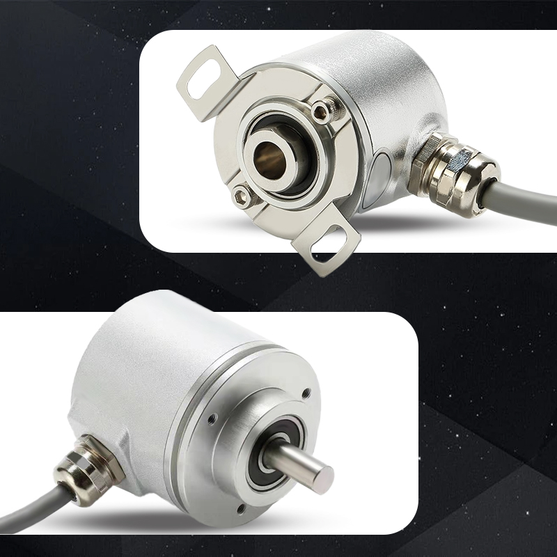
Appearance structure | 60mm outer diameter, solid shaft, blind hole shaft | Reverse polarity protection | Yes |
Connection type | 8-core shielded cable or aviation plug | Operating temperature | -40℃~85℃ |
Wiring Diagram
Function | Six-channel without settings | Six-channel band setup | Three channels without settings | Three-channel band set |
Vcc | Brown | Brown | Brown | Brown |
GND | White | White | White | White |
/A | Green | Red | ||
/B | Yellow | Purple | ||
/Z | Blue | Blue | ||
A | Gray | Gray | Gray | Gray |
B | Pink | Pink | Pink | Pink |
Z | Black | Black | Black | Black |
RS485A | Green (RS485A) | Green (RS485A) | ||
RS485B | Yellow (RS485B) | Yellow (RS485B) | ||
Shield | Network | Network |
The command to modify the number of pulses with RS485 is as follows:
Configuration: baud rate 19200, data bit 8, stop bit 1, no checksum,
Command: 44 00 01 46 31 36 33 38 34 0D (pulse number 16384)
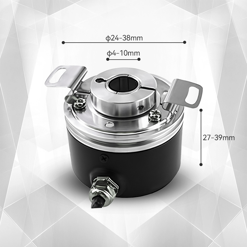
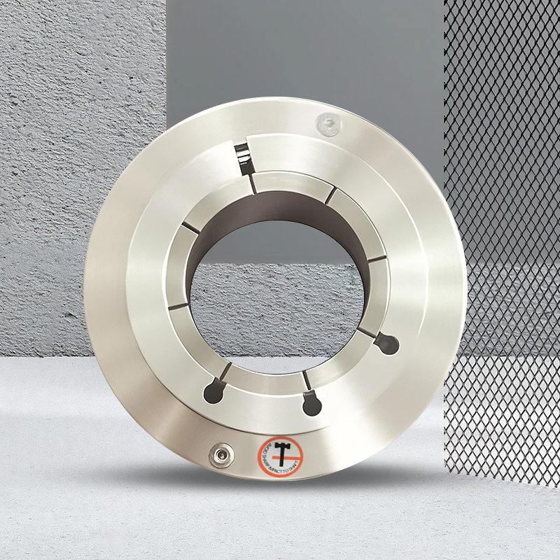
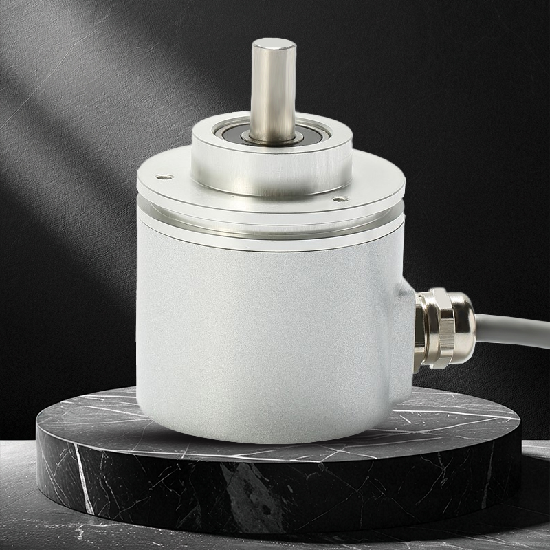
Mechanical Dimensions
Clamping synchronous flange (cable output or plug output optional)
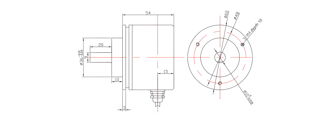
60mm outer diameter 6/8/10mm shaft diameter optional 20mm shaft length Axial outlet optional
Clamping flange (cable output or plug output optional)
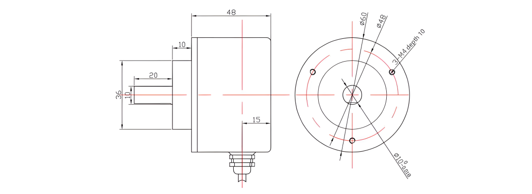
60mm outer diameter 6/8/10mm shaft diameter optional 20mm shaft length Axial outlet optional
Synchronous flange / servo flange cable output or plug output optional)
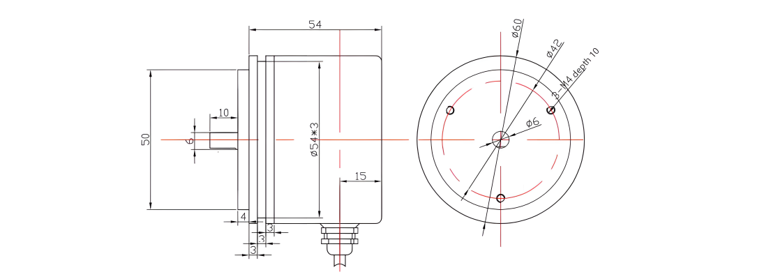
60mm outer diameter 6mm shaft diameter 10mm shaft length Axial outlet optional
Blind hole type / semi-through hole flange cable output or plug output optional)
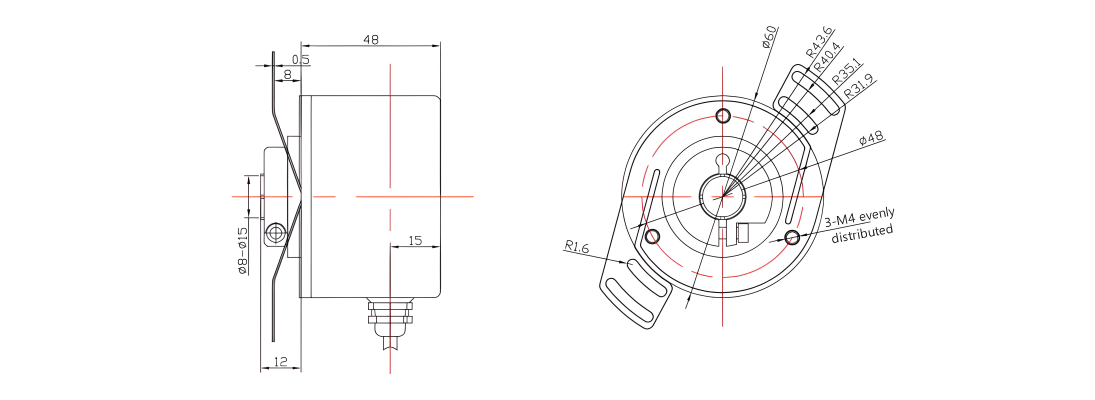
60mm outer diameter 8-15mm hole diameter optional 20mm hole depth Axial outlet optional
Output phase

Output circuit
Output circuit |
|
|
|
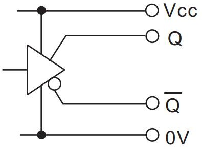
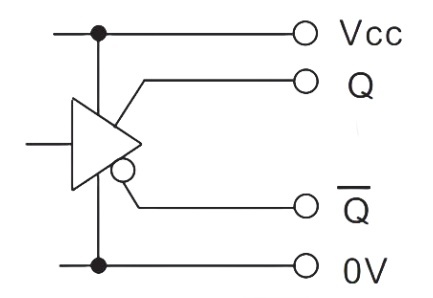
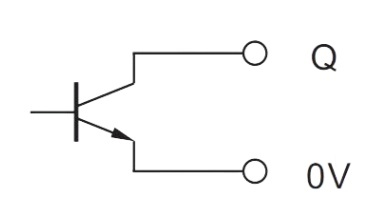
TTL | HTL | Open collector | |
Power supply voltage | 5±0.25V or 10~30V | 4.75~30V | 4.75~30V |
Number of signals | A, B, Z, /A, /B, /Z | A, B, Z, /A, /B, /Z | A, B, Z, (/A, /B, /Z) |
Current consumption | Max.50mA | Max.50mA | Max.30mA |
Allowable load | Min.20mA | Min.20mA | Min.20mA |
Signal high level | Min.2.5V | Min.Vcc*70% | Min.Vcc*70% |
Signal low level | Max.0.5V | Max.0.5V | Max.0.5V |
Power supply protection | Yes | Yes | Yes |
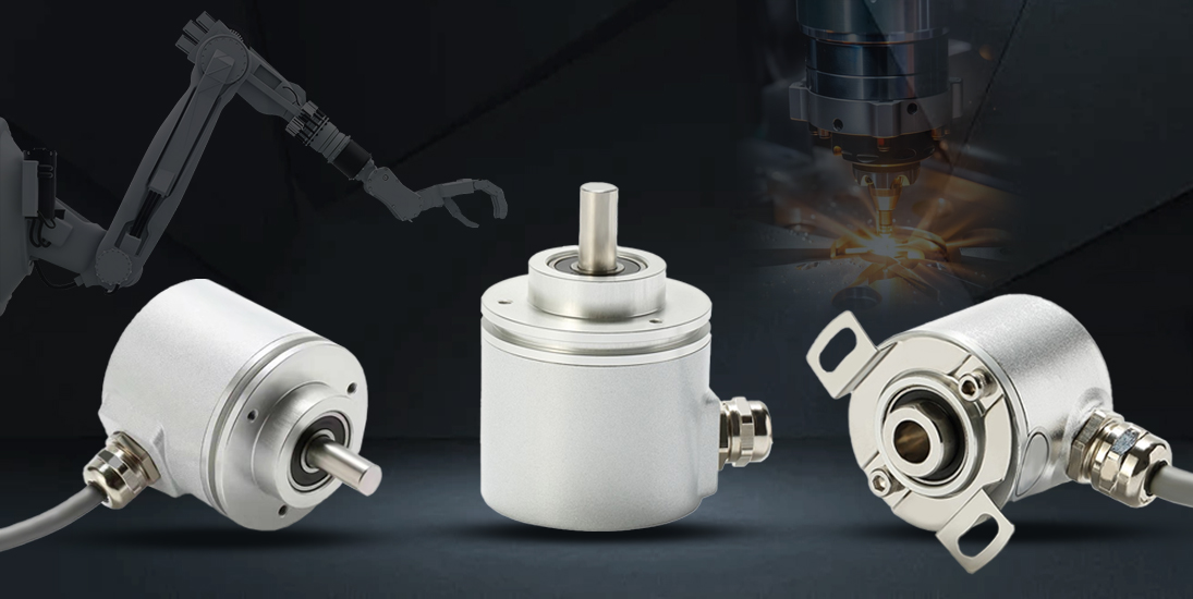
Product Display
RS485 programmable: pulse number 1-16384 can be set arbitrarily
Wide voltage adaptation: 4.75-30VDC power supply compatible
Multiple output modes: push-pull HTL, TTL, open collector optional
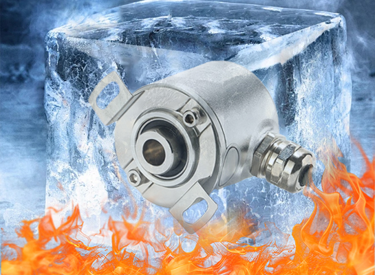
Strong shock and vibration resistance: 100g shock, 20g vibration tolerance
Wide temperature operation: -40℃~85℃ environment applicable
High protection level: up to IP68 dust and water proof
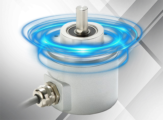
Safety lock bearing: anti-vibration and anti-installation error
High response frequency: 1MHz fast feedback
Flexible structure: 60mm outer diameter, solid/blind hole shaft optional
Reverse polarity protection: circuit safety design
Quality Control
The quality of encoders is directly related to the stability and reliability of industrial automation systems. We have built a full-process quality control system, strictly screening suppliers from raw material procurement to ensure that the performance of core components meets standards; in the production process, we use high-precision equipment and standardized processes, and cooperate with online detection technology for real-time monitoring; in the finished product stage, we conduct rigorous tests such as high and low temperature, electromagnetic compatibility, and life aging to eliminate performance risks. Each encoder has passed multiple quality inspection levels, and its excellent quality has laid a solid foundation for intelligent manufacturing, providing customers with long-term and stable use guarantees.

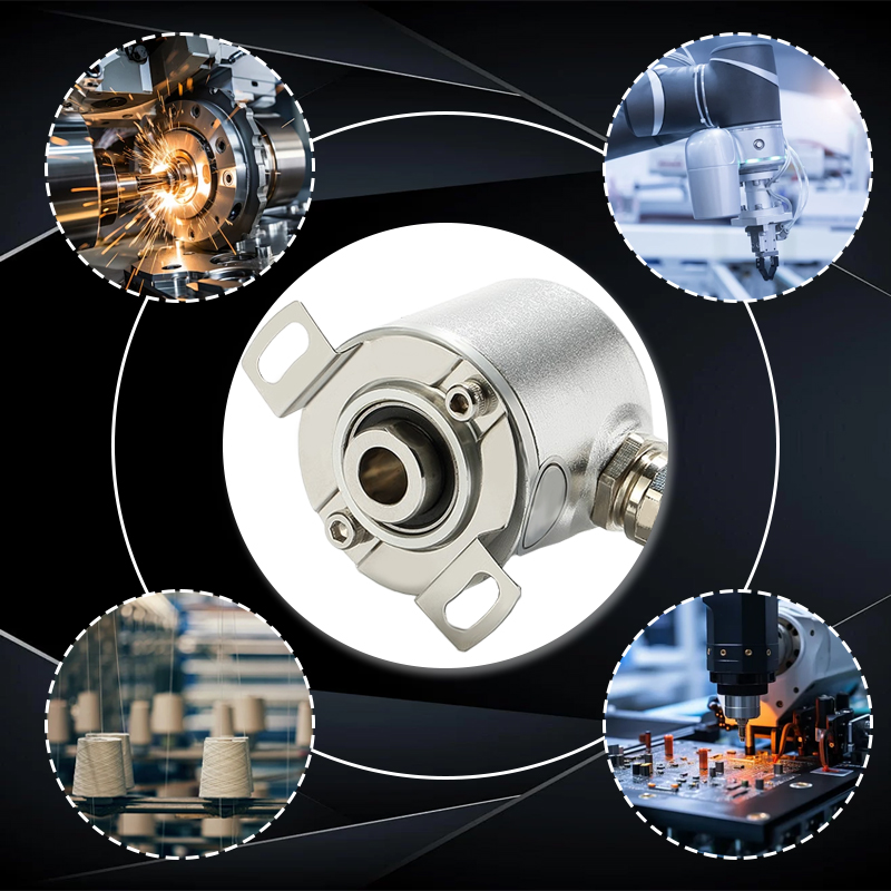
Application Cases
Programmable incremental encoders are suitable for industrial automation scenarios such as machine tool spindle speed monitoring and robot joint position feedback. They can resist vibration in conveyor line speed control, achieve high-precision positioning in servo motor systems, and can also be used for drum speed detection in a wide temperature environment of textile machinery, meeting the automation control needs of multiple industries.

Precautions
(If the encoder is damaged due to failure to read the precautions carefully, it is not covered by the warranty.)
✱The encoder is a precision instrument. Please do not knock, hit or drop the encoder, especially at the end of the shaft. Please handle it with care.
✱Ensure that the encoder power supply is within the range of 5.75-30Vdc and isolate it to prevent the large starting electrical in the power grid from impacting the encoder.
✱In an environment with strong electromagnetic interference, the recommended dedicated line should be used to extend the signal line, such as a twisted shielded cable.
✱The encoder signal line should be well grounded: within a short distance of 2 meters, both ends of the shielding net inside the cable should be grounded; for a longer distance, the encoder metal shell is grounded, the encoder's own cable shielding net is suspended, and the signal extension cable shielding net is grounded at one end at the signal receiving end; if the signal cable is long or used outdoors, the signal cable should be covered with a metal iron pipe, and both ends of the metal pipe should be grounded for use.
✱The pulse signal line is voltage-carrying. When using it, the signal line should be prevented from being short-circuited or short-circuited with the power supply, and the unused signal line should be insulated; it is forbidden to plug and unplug with power on, and ensure that all cores of the cable are connected at the same time when the power is on. The encoder must be powered off and there must be no static welding or connection. First weld or connect the 0V line; when wiring, do not pull the cable violently.
✱The protection level of the encoder is IP65, which can be used in waterproof, but the encoder shaft should not be immersed in water.
✱A dedicated flexible coupling should be used for the connection between the encoder shaft and the machine. ZH69401 is recommended.
Ordering data
Description | Example:ZH | M | 58 | 16384 | E | CS | 10 | H | CSB |
Pulse encoder | ZH | X | 58 | X | X | X | X | X | X |
Shaft type | Shaft type | M | |||||||
Hole type | H | ||||||||
Resolution | 1-16384 | 16384 | |||||||
Power supply | 5Vdc | A | |||||||
4.75~30Vdc | E | ||||||||
Flange | Clamping | 32 | |||||||
Clamping synchronization | 39 | ||||||||
Synchronous | 15 | ||||||||
Blind hole sleeve | 28 | ||||||||
Shaft (hole) diameter | Ø6mm | 0S | |||||||
Ø8mm | 0E | ||||||||
Ø10mm | 0T | ||||||||
Ø12mm (limited to sleeve) | TT | ||||||||
Ø15mm (limited to sleeve) | TF | ||||||||
Ø16mm (limited to sleeve) | TS | ||||||||
Output signal | HTL | H | |||||||
TTL | T | ||||||||
Open collector 3 channels | O | ||||||||
Open collector 6 channels | 01 | ||||||||
Connection | Plug, axial | GA | |||||||
Plug, radial | |||||||||
1m cable, axial | ACO(A) | ||||||||
1m cable, radial | CSB(B) |