
Product Description
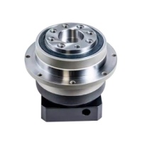
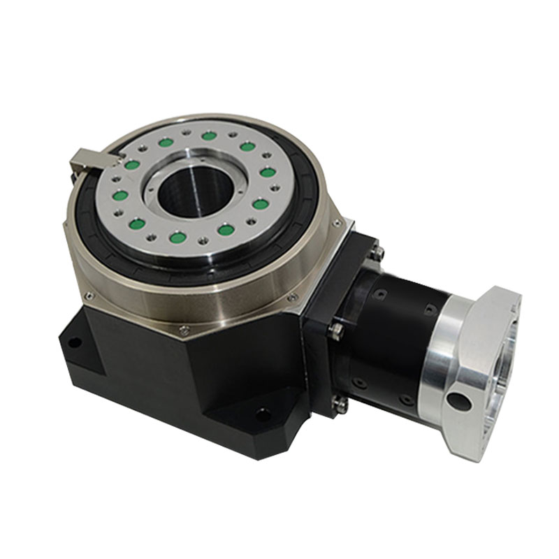
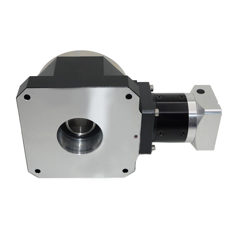
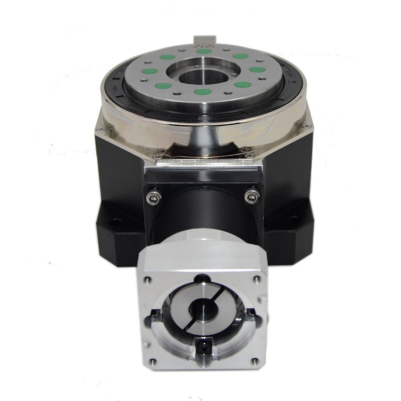
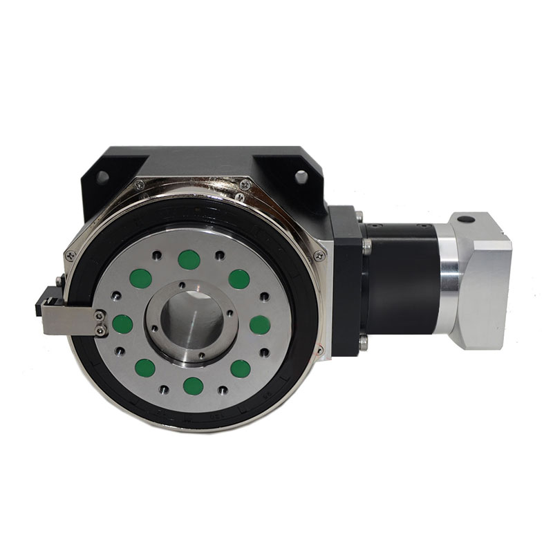
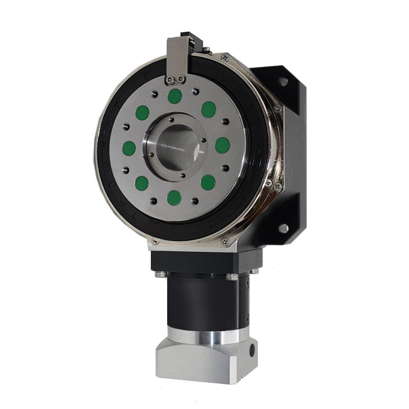
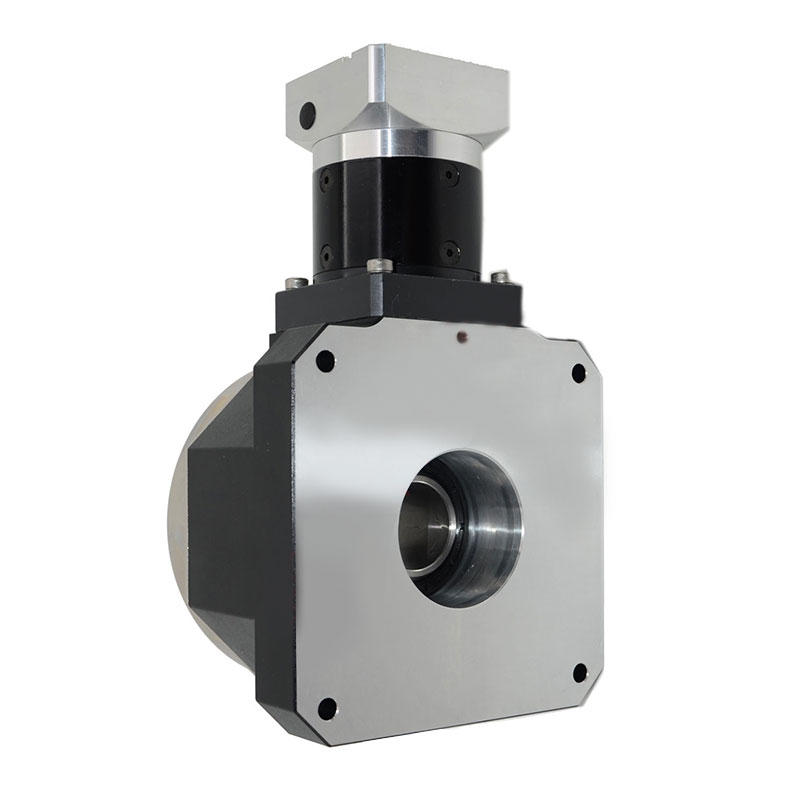
The RR right-angle hollow rotary platform, with its unique right-angle structural design, provides more flexibility for the equipment space layout and is suitable for a variety of installation scenarios. The platform is made of high-quality materials and exquisite craftsmanship, with excellent high rigidity, can easily cope with heavy-load conditions, and ensure stable and reliable operation. Its high-precision transmission system achieves precise positioning and smooth operation, with high repeat positioning accuracy, effectively reducing errors, and meeting the needs of various precision operations. At the same time, it has strong high torque output performance and efficient power transmission, and can maintain excellent performance even in complex working environments. The low side clearance further improves the accuracy of motion control. The hollow structure in the middle facilitates the insertion and arrangement of cables, air pipes, etc., simplifies the internal wiring of the equipment, saves space and is easy to maintain. It is widely used in electronic manufacturing, mechanical processing, automated production lines and other fields, and is an ideal choice for improving equipment performance and production efficiency.
Functional Features
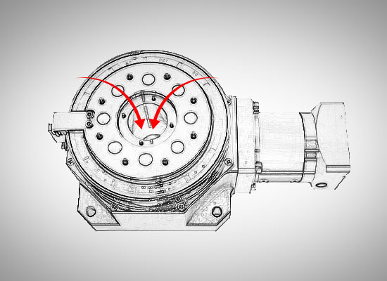
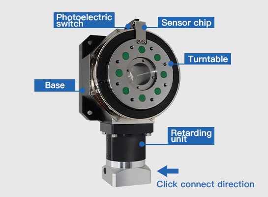
Hollow structure, convenient for threading
The turntable of the RR series servo rotary platform is a hollow structure, and the servo motor is connected to the side, which is convenient for the installation of air pipes and wires in the jig.

High rigidity
The turntable of the RR series servo rotary platform is supported by a set of precision cross roller bearings. The rollers in the bearings are staggered at 90 degrees, and the roller diameter is slightly larger than the raceway size between the inner and outer rings of the bearings, so that there is a preload between the inner and outer rings and rollers of the cross roller bearings. The turntable of the servo rotary platform supported by the bearings can withstand various moments such as radial, axial, and overturning, and its rigidity is more than 10 times that of traditional bearings.

High rotation accuracy
After the RR series servo rotary platform is assembled, the outer diameter and end face of the turntable are ground again with the cross roller bearing of the platform as the rotation center to ensure the coaxiality of the turntable, end runout and other geometric tolerances.

Large torque, low backlash
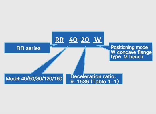
RR series servo rotary platform adopts planetary reduction to increase output torque, with reduction ratio from 1 to 1536, and a wide output torque range, which can meet various torque requirements. In addition, by changing the center distance of the gear to eliminate the backlash, the reverse backlash of the SR series servo rotary platform is close to zero backlash, and the accuracy is comparable to that of DD motor.

Built-in zero point switch, optional limit switch
RR series servo rotary platform is equipped with photoelectric switch and sensor sheet as standard, and optional positive and negative limit switches are available to facilitate zero point control in electrical and simplify mechanical design process.
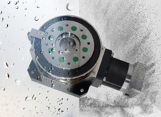
Dustproof and waterproof
RR series servo rotary platform adopts skeleton oil seal to isolate the inside and outside of the platform, and the dustproof and waterproof level reaches IP65, which meets the requirements of working in harsh environments such as dust, splashing water, and heavy humidity.
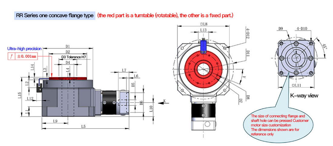
Dimensional drawing
Product Model | RR40 | RR60 | RR80 | RR120 | RR160 | RR250 | Reduction ratio/Number of stages | ||
Design load bearing | 15Kg | 40Kg | 80Kg | 200Kg | 800Kg | 3500Kg | |||
D1 | Boss diameter | 98 | 125 | 172 | 220 | 250 | 558 | ||
D2 | Turntable diameter | Φh7 | 75 | 95 | 130 | 170 | 200 | 480 | |
D3 | Inner diameter of turntable | ΦH 7 | 30 | 45 | 70 | 80 | 105 | 330 | |
D4 | Threading hole diameter | Φ | 20 | 30 | 50 | 50 | 50 | 260 | |
D5 | Motor shaft hole | ΦF7 | 8 | 14 | 19 | 22 | 35 | 35 | |
D6 | Motor positioning circle diameter | ΦH 7 | 30 | 50 | 70 | 110 | 114.3 | 114.3 | |
D7 | Rotary table screw hole indexing circle | Φ | 59 | 75 | 106 | 138 | 160 | 430 | |
D8 | Turntable screw hole | 8-M4↓8 | 8-M5↓10 | 10-M6↓12 | 12-M8↓16 | 12-M10↓20 | 24-M12↓24 | ||
D9 | Motor screw hole pitch circle | Φ | 45 | 70 | 90 | 145 | 200 | 200 | |
D10 | Motor screw hole | M4↓8 | M4↓8 | M5↓10 | M8↓16 | M12↓24 | M12↓24 | ||
D11 | Base screw hole pitch circle | Φ | 120 | 150 | 205 | 265 | 300 | 650 | |
D12 | Base screw hole | Φ5.5Through Hole | Φ6.6Through Hole | Φ9Through Hole | Φ11Through Hole | Φ14Through Hole | Φ22Through Hole | ||
L1 | Base thickness | 20 | 25 | 30 | 45 | 60 | 70 | ||
L2 | Boss thickness | 17.7 | 19.7 | 24.7 | 29.7 | 31.7 | 50 | ||
L3 | Turntable protrusion | 6.5 | 6.5 | 9 | 12.5 | 18.5 | 12 | ||
L4 | Inner circle depth of turntable | 4 | 5 | 6 | 8 | 10 | 12 | ||
L5 | Overall length of platform | 174.5 | 222 | 296.5 | 366.5 | 464 | 759 | Level 1 | |
189 | 237 | 314 | 390 | 503.5 | 803.5 | Level 2 | |||
203.5 | 251.5 | 331.5 | 412 | 542 | 837.5 | Level 3 | |||
L6 | Motor boss depth | 3.5 | 4 | 5 | 8 | 5 | 5 | ||
L7 | Motor shaft hole depth | 27 | 32 | 41 | 60 | 83 | 83 | ||
L8 | Base width | 105 | 130 | 180 | 225 | 260 | 560 | ||
L9 | Distance from turntable center | 52.5 | 65 | 90 | 112.5 | 130 | 280 | ||
L10 | Motor center distance | 27.5 | 35 | 49.5 | 70 | 110 | |||
L11 | Motor side length | 40 | 60 | 80 | 130 | 180 | 180 | ||
L12 | Switch thickness | 13.4 | 13.4 | 13.4 | 13.4 | 13.4 | 13.4 | ||
L13 | Switch width | 26 | 26 | 26 | 26 | 26 | 26 | ||
L14 | Sensor plate position | 3 | 3 | 4 | 4 | 4 | 1 | ||
L15 | Platform height | 81.5 | 98.5 | 135 | 184.5 | 242.5 | 287 | ||
V | Hole Angle | 22.5° | 22.5° | 0° | 15° | 15° | 7.5° | ||
B | Base chamfer | C | 10 | 12.5 | 15 | 16.5 | 18 | 40 |
Product parameters
Product model | RR40 | RR60 | RR80 | RR120 | RR160 | RR250 | Reduction ratio | Number of stages |
Rated output torque (Nm) | 24 | 54 | 120 | 375 | 1200 | 3150 | 9 | Level 1 |
54 | 120 | 330 | 780 | 2400 | 5340 | 12 | ||
48 | 108 | 270 | 690 | 2100 | 4800 | 15 | ||
15 | 45 | 150 | 360 | 1350 | 2850 | 24 | ||
24 | 54 | 120 | 375 | 1200 | 3150 | 27 | Level 2 | |
54 | 120 | 330 | 780 | 2400 | 5340 | 36 | ||
48 | 108 | 270 | 690 | 2100 | 4800 | 45 | ||
54 | 120 | 330 | 780 | 2400 | 5340 | 48 | ||
54 | 120 | 330 | 780 | 2400 | 3000 | 60 | ||
48 | 108 | 270 | 690 | 2100 | 5340 | 75 | ||
54 | 120 | 330 | 780 | 2400 | 4800 | 96 | ||
48 | 108 | 270 | 690 | 2100 | 4800 | 120 | ||
15 | 45 | 150 | 360 | 1350 | 3000 | 192 | ||
54 | 120 | 330 | 780 | 2400 | 5340 | 180 | Level 3 | |
54 | 120 | 330 | 780 | 2400 | 5340 | 240 | ||
54 | 120 | 330 | 780 | 2400 | 5340 | 300 | ||
48 | 108 | 270 | 690 | 2100 | 5340 | 360 | ||
54 | 120 | 330 | 360 | 2400 | 5340 | 480 | ||
48 | 108 | 270 | 690 | 2100 | 4800 | 600 | ||
54 | 120 | 330 | 780 | 2400 | 5340 | 768 | ||
48 | 108 | 270 | 690 | 2100 | 4800 | 960 | ||
15 | 45 | 150 | 360 | 1350 | 3000 | 1536 | ||
Fault stop torque | 2 times rated output torque | |||||||
Product model | RR40 | RR60 | RR80 | RR120 | RR160 | RR250 | 级数 | |
Maximum radial force (N) | 5800 | 6700 | 11000 | 16300 | 26700 | 116000 | / | |
Maximum axial force (N) | 5800 | 6700 | 11000 | 16300 | 26700 | 116000 | / | |
Design load bearing (kg) | 15Kg | 40Kg | 80Kg | 200Kg | 800Kg | 3500Kg | / | |
Maximum overturning moment (NM) | 435 | 636 | 1430 | 2771 | 5340 | 55680 | / | |
Full load efficiency (%) | 96 | Level 1 | ||||||
94 | Level 2 | |||||||
90 | Level 3 | |||||||
Average lifespan (h) | 20000 | |||||||
Weight (Kg) | 2.2 | 4.4 | 11 | 21.4 | 41.8 | 282 | Level 1 | |
2.3 | 4.6 | 11.3 | 23.3 | 46.8 | 326.5 | Level 2 | ||
2.4 | 4.8 | 11.8 | 25.3 | 51.8 | 360.5 | Level 3 | ||
Product Model | RR40 | RR60 | RR80 | RR120 | RR160 | RR250 | Reduction ratio |
Moment of Inertia(kg·cm²) | 0.033 | 0.147 | 0.839 | 2.864 | 13.219 | 79.314 | 9 |
0.023 | 0.097 | 0.542 | 1.864 | 8.101 | 48.606 | 12 | |
0.02 | 0.079 | 0.459 | 1.559 | 6.187 | 37.122 | 15 | |
0.017 | 0.065 | 0.388 | 1.314 | 4.608 | 27.648 | 24 | |
0.029 | 0.13 | 0.734 | 2.599 | 12.044 | 72.264 | 27 | |
0.028 | 0.125 | 0.711 | 2.526 | 12.207 | 73.242 | 36 | |
0.023 | 0.075 | 0.699 | 2.49 | 12.157 | 72.942 | 45 | |
0.022 | 0.086 | 0.492 | 1.722 | 7.349 | 44.094 | 48 | |
0.019 | 0.074 | 0.432 | 1.474 | 6.534 | 39.204 | 60 | |
0.019 | 0.074 | 0.432 | 1.462 | 5.703 | 34.218 | 75 | |
0.017 | 0.063 | 0.382 | 1.275 | 6.239 | 37.434 | 96 | |
0.016 | 0.063 | 0.382 | 1.275 | 5.177 | 31.062 | 120 | |
0.016 | 0.063 | 0.382 | 1.274 | 4.411 | 26.466 | 192 | |
0.028 | 0.074 | 0.5 | 2.52 | 7.352 | 44.112 | 180 | |
0.019 | 0.074 | 0.49 | 1.47 | 7.351 | 44.106 | 240 | |
0.019 | 0.074 | 0.431 | 1.46 | 7.253 | 43.518 | 300 | |
0.028 | 0.063 | 0.686 | 2.45 | 7.155 | 42.93 | 360 | |
0.016 | 0.063 | 0.382 | 1.274 | 6.37 | 38.22 | 480 | |
0.016 | 0.063 | 0.382 | 1.274 | 6.076 | 36.456 | 600 | |
0.016 | 0.063 | 0.382 | 1.274 | 5.586 | 33.516 | 768 | |
0.016 | 0.063 | 0.382 | 1.274 | 5.292 | 31.752 | 960 | |
0.016 | 0.063 | 0.382 | 1.274 | 5.096 | 30.576 | 1536 | |
Return clearance | ≤0.6arc minutes | ≤0.6arc minutes | ≤0.6arc minutes | ≤0.6arc minutes | ≤0.6arc minutes | ≤1arc minutes | Level 1 |
≤1arc minutes | ≤1arc minutes | ≤1arc minutes | ≤1arc minutes | ≤1arc minutes | ≤2arc minutes | Level 2 | |
≤2arc minutes | ≤2arc minutes | ≤2arc minutes | ≤2arc minutes | ≤2arc minutes | ≤5arc minutes | Level 3 |
Product Model | RR40 | RR60 | RR80 | RR120 | RR160 | RR250 |
Turntable end runout | ±0.001 | ±0.001 | ±0.001 | ±0.001 | ±0.001 | 士0.01 |
Radial runout of turntable | ±0.001 | ±0.001 | ±0.001 | ±0.001 | ±0.001 | 士0.01 |
Torsional rigidity | 0.7 | 1.8 | 4.4 | 9.2 | 26.7 | 58 |
Noise | 55 | 58 | 60 | 65 | 70 | 80 |
Rated input speed | 4500 | 4000 | 4000 | 3500 | 3000 | 3000 |
Rated output speed | 300 | 300 | 300 | 300 | 300 | 300 |
Selection calculation
I. Selection steps
1. According to the actual installation requirements and accuracy requirements, select one of the models CR, SR, and RR
2. Calculate the load inertia, and calculate the acceleration torque according to the speed. Refer to the "Rated output torque" column in the sample book table to select the size that meets the torque requirements
3. According to the total load weight, refer to the "Design load-bearing" column in the sample book table, and select the appropriate size in combination with the torque requirements
4. Select the motor according to the size of the rotating platform
5. According to the load inertia and the motor rotor inertia, calculate the minimum reduction ratio required to meet the inertia matching
6. According to the acceleration torque and motor torque, calculate the minimum reduction ratio to meet the torque requirements
7. According to the actual speed requirements and the rated speed of the motor, calculate the maximum reduction ratio to meet the speed requirements
8. According to the three calculated reduction ratios, select the appropriate reduction ratio according to the reduction ratio table attached to the sample book
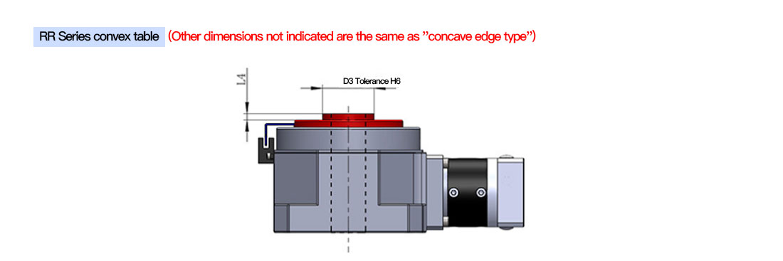
9. According to the needs, select a concave edge turntable or a convex platform turntable, and the selection is over
II. Selection Example
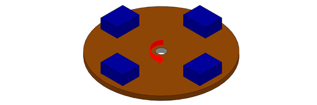
Example 1: Make a four-station indexing plate, total load weight: 20KG, load diameter 400mm, load speed: 90 degrees per second, required repeatability: plus or minus 0.02mm, this device is installed on the XY cross platform, and the height dimension of the rotating platform cannot be too large
Calculation is as follows:
1. The repeatability of plus or minus 0.02 is a high-precision requirement, so only SR or RR can be selected. The height dimension cannot be too large, so only the RR series rotating platform can be selected
2. According to the load weight and size, the load inertia is calculated as: 0.4kgM², the acceleration time is set to 0.1 seconds, the uniform speed time is: 0.8 seconds, the deceleration time is: 0.1 seconds, and the acceleration torque is calculated to be: 6.98NM. The models that meet this torque requirement are: SR40, SR60, SR80, SR120, SR160, SR250.
3. The total load weight is: 20KG. According to the "Design Load-bearing" table in the sample book, the load-bearing capacity of RR60 is: 40KG, which meets the requirements
4. The motor interface length of RR60 is: 60mm, so a 400W servo motor is selected. In this example, a Panasonic 400W servo motor (high inertia) is selected
5. According to the load inertia (0.4kgM²) and the 400W (high inertia) Panasonic servo inertia (0.000067kgM²), the load inertia is not greater than 15 times the motor inertia, and the minimum reduction ratio required to meet the inertia matching is calculated as: 19.95
6. According to the acceleration torque (6.97NM) and the rated torque of the 400W servo motor (1.3NM), the minimum reduction ratio that meets the torque requirement is calculated as: 5.4
7. According to the required speed (90 degrees per second) and the rated speed of the 400W servo (3000 revolutions per minute), the maximum reduction ratio that meets the speed requirement is calculated as: 180
8. Combined with the three reduction ratio limit ranges, refer to the reduction ratio listed in the sample book, and select the reduction ratio as: 24
9. According to the installation requirements, select the concave edge turntable, and finally determine the model as: RR60-24W
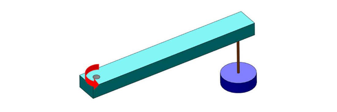
Example 2: Make a robotic arm with an arm length of 1.3m and an arm weight of 22KG. The weight of the workpiece to be grabbed is: 1.5KG. The required speed is 90 degrees per second. Precise positioning is required, and the motor is installed downward.
The calculation is as follows:
1. Precise positioning is required, so only SR or RR can be selected: the motor is required to be installed downward, so only the SR series rotary platform can be selected
2. The load inertia is composed of the cantilever inertia and the workpiece inertia: 12.39+2.54=14.93kgM², the acceleration time is set to 0.1 seconds, the uniform speed time is: 0.8 seconds, the deceleration time is: 0.1 seconds, and the calculated acceleration torque is: 260.4NM. The models that meet this torque requirement are: SR80, SR120, SR160
3. The total load weight is: 22+1.5=23.5KG. According to the "Design Load-bearing" table column in the sample book, SR60, SR80, SR120, SR160, SR250
all meet the requirements. Combined with the torque requirements, it is more appropriate to choose SR80
4. The motor interface length of SR80 is: 80mm, so a 750W servo motor is selected. In this example Select Panasonic 750W servo motor (high inertia)
5. According to the load inertia (14.93kgM²) and the 750W (high inertia) Panasonic servo inertia (0.000151kgM²), the load inertia is not greater than 15 times the motor inertia, and the minimum reduction ratio required to meet the inertia matching is calculated to be: 81.2
6. According to the acceleration torque (260.4NM) and the 750W servo motor torque (2.4NM), the minimum reduction ratio to meet the torque requirement is calculated to be: 108.5
7. According to the required speed (90 degrees per second) and the rated speed of the 750W servo (3000 revolutions per minute), the maximum reduction ratio to meet the speed requirement is calculated to be: 180
8. Combined with the three reduction ratio limit ranges, refer to the reduction ratio listed in the sample book, and select the reduction ratio: 120
9. According to the installation requirements, select the concave edge turntable, and finally determine the model: SR80-120W
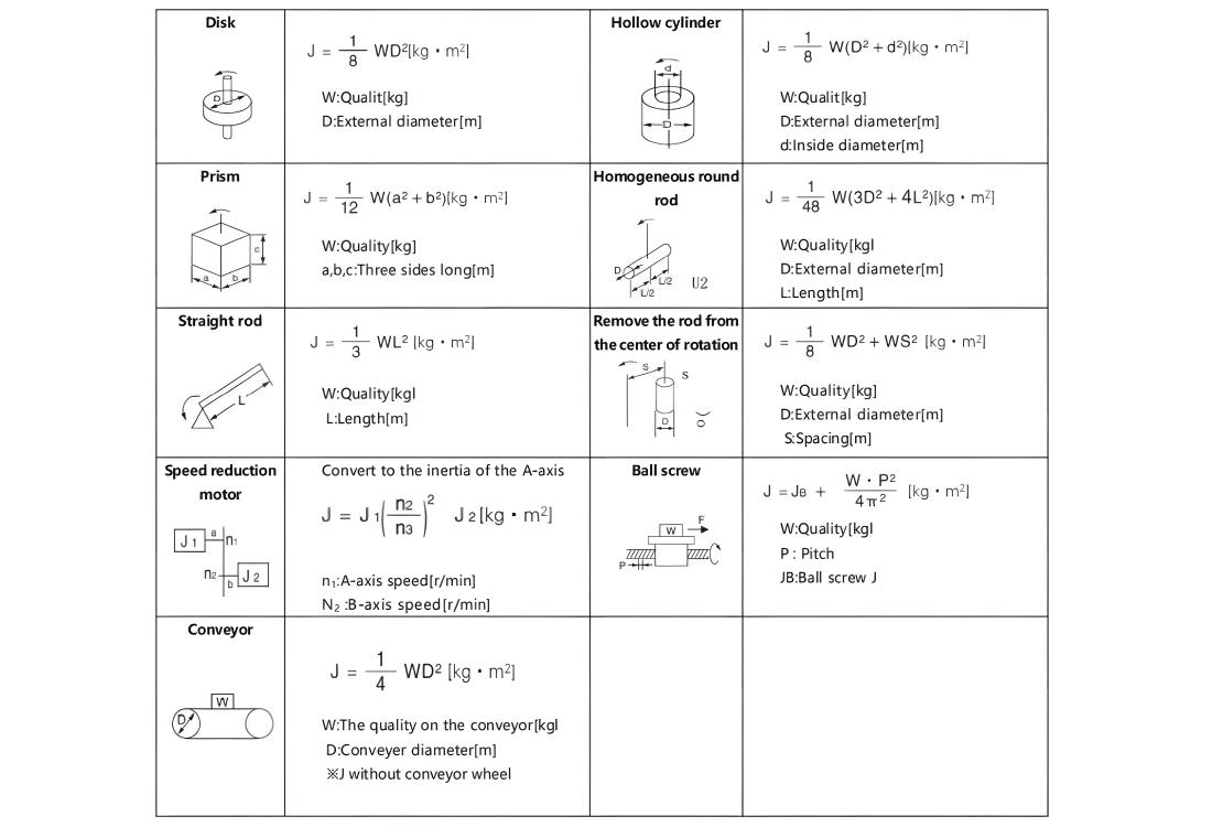
III.Common inertia calculation formulas
Application
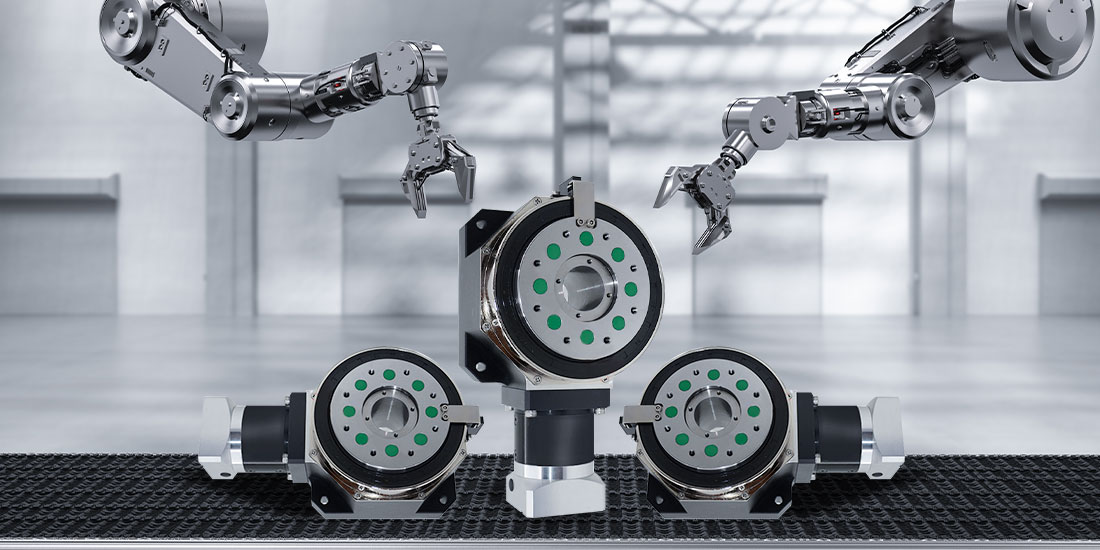
In the mold engraving process in the field of mechanical processing, the platform carries the mold blank, and through precise rotation, the engraving equipment completes the engraving of complex patterns and designs on the mold surface, ensuring the quality and accuracy of the mold.
In the self-logistics sorting automated production line, the platform cooperates with the robotic arm to grab the goods, and through rotation, the goods are accurately placed in different sorting areas to improve the efficiency and accuracy of logistics sorting.
In the winding process of lithium batteries for new energy, the platform drives the pole piece winding device to achieve tight and uniform winding of the pole piece, ensuring the stability of lithium battery performance and improving battery production consistency.

Quality Assurance
Product design and development: During the design phase of the central control rotary platform, a team of professional engineers gathered together to use advanced computer-aided design (CAD) and simulation analysis software to perform fine simulation and optimization of core parts such as product structure, power transmission, and control logic to ensure the reliability and stability of product performance from the source. All design plans must undergo multiple rounds of internal review and test verification before they can enter the production stage.
Raw material procurement: Strictly screen raw material suppliers to establish long-term, stable and high-standard cooperative relationships. For each batch of raw materials, strict quality inspections are carried out, covering the composition analysis of metal materials, mechanical performance testing, electrical parameter testing of electronic components, reliability testing, etc. Only raw materials that meet or exceed industry standards will be allowed to be put into production to ensure the basic quality of the product.
Production process control: The production workshop operates in accordance with a strict quality management system, introduces automated production equipment and high-precision testing instruments, and realizes the standardization and refinement of the production process. At each key node of production, quality inspection points are set up to conduct real-time sampling and full inspections of semi-finished products, including component processing accuracy inspection, assembly quality inspection, and initial electrical performance testing. For quality problems that occur during the production process, the traceability and rectification mechanism is immediately activated to ensure that the problematic products do not flow into the next link.
Finished product inspection: Each central control rotary platform must undergo a comprehensive and rigorous finished product inspection process before leaving the factory. Inspection items include but are not limited to no-load operation test, full-load operation test, positioning accuracy test, repeated positioning accuracy test, noise and vibration test, electrical safety performance test, etc. Only equipment whose indicators fully meet the product quality standards will be labeled as qualified and allowed to leave the factory.
After-sale guarantee
If a product fails, our after-sales team will respond immediately and quickly arrange for professional technicians to communicate with you to understand the details of the failure. We will provide you with remote technical guidance and assist you in solving the problem according to the specific situation. At the same time, we also provide you with regular return visits to understand the use of the product and collect your opinions and suggestions in order to continuously optimize products and services. When the product is upgraded, we will also notify you in a timely manner and provide you with corresponding technical support and solutions to keep your equipment in good performance.