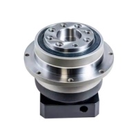

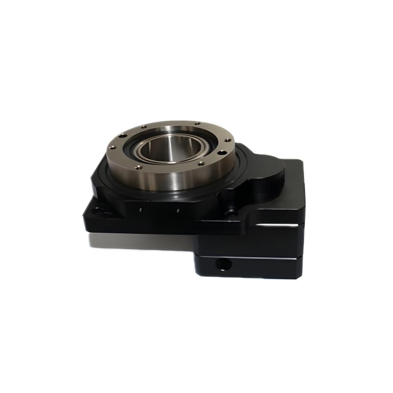
产品描述
DK系列中空旋转平台具备卓越性能。旋转盘面可直接锁固工作物,极大提升工件装载便利性。其动转动作平稳顺畅,定位迅速精准,定位精度小于一分 ,重复精度可选 ±5 秒。采用中空式设计,无论是配线还是配管都极为方便。可适配各种厂牌的伺服马达或步进马达驱动,满足多样化工业需求,广泛应用于自动化设备、电子制造等领域。
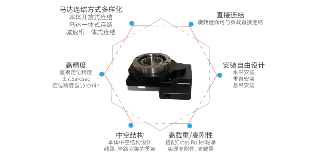
功能特点
工作物可直接锁固
旋转盘面可直接锁固工作物,提升工件装载之方便性。
动转动作平稳
盘面转动平稳、顺畅,且定位快速。
配线方便
此旋转平台为中空式设计,无论是配线或配管均方便。
试用各种马达
中空旋转平台可采用各种厂牌之伺服马达或步进马达驱动。
高精度
定位精度小于一分。
重复精度可选±5秒。
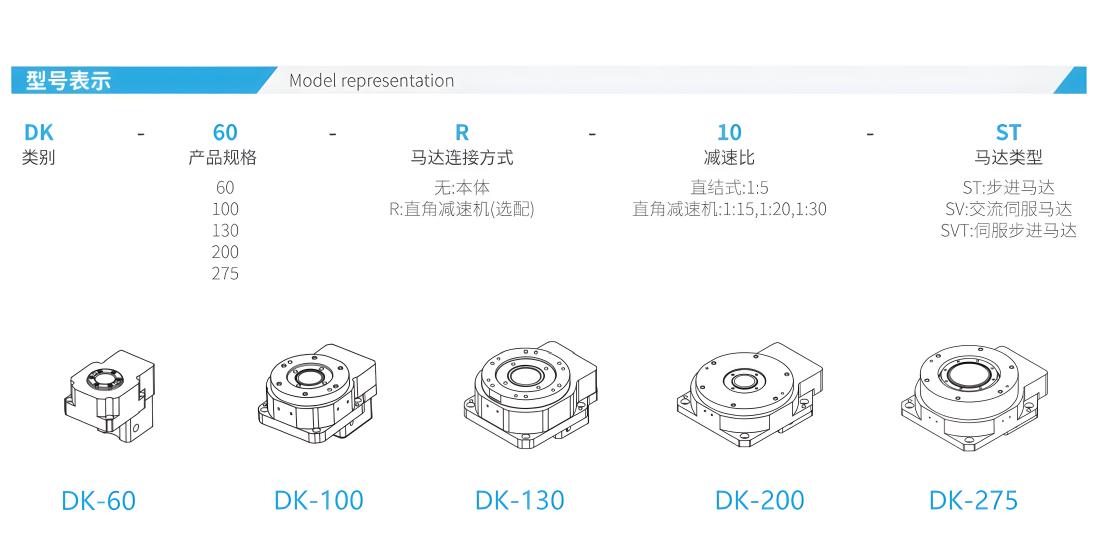
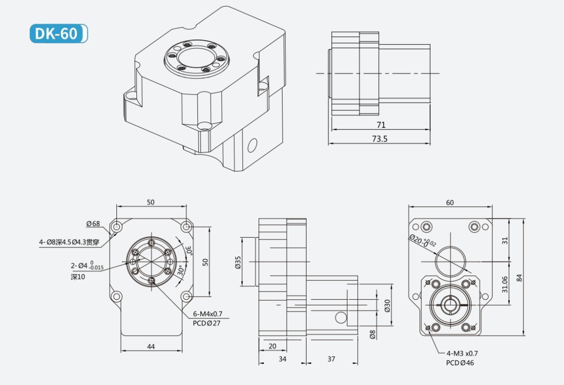
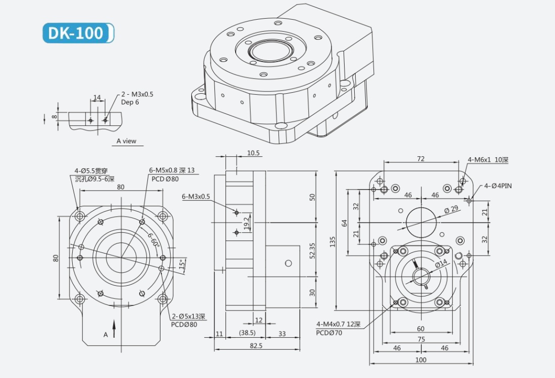
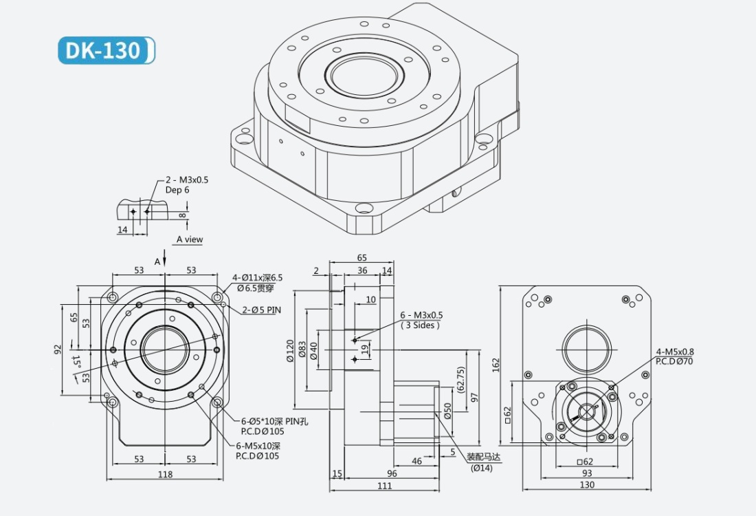
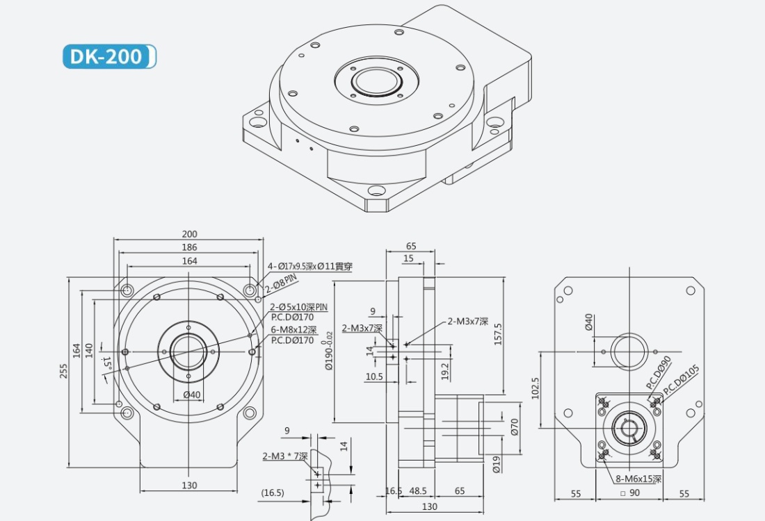
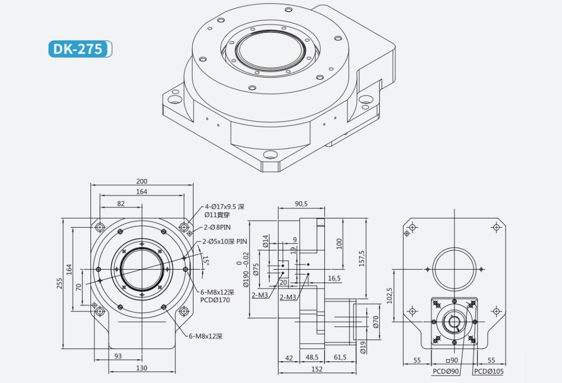
尺寸图
产品参数
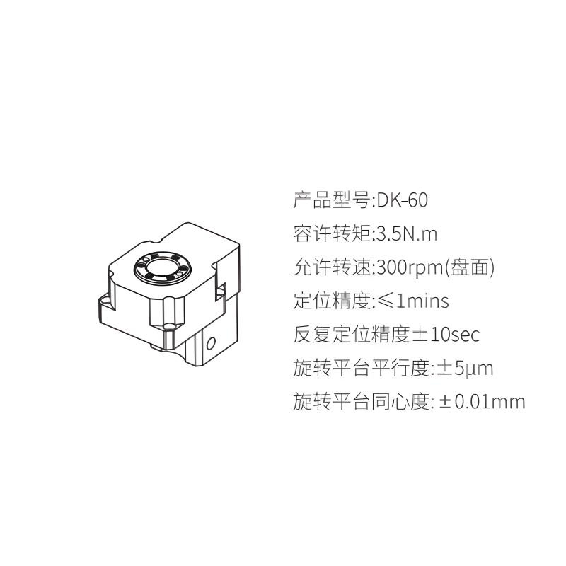
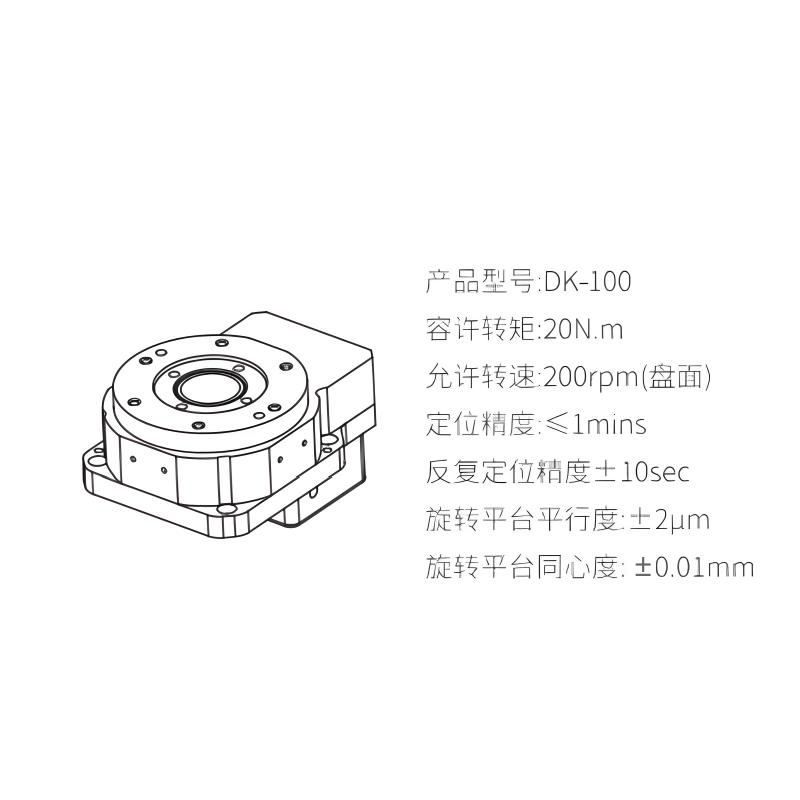
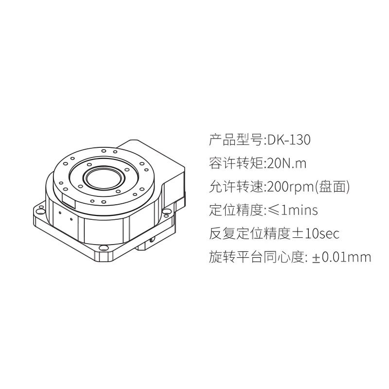
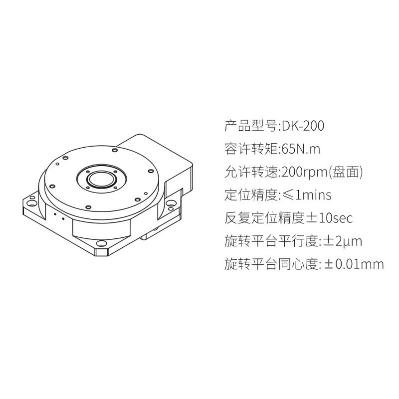
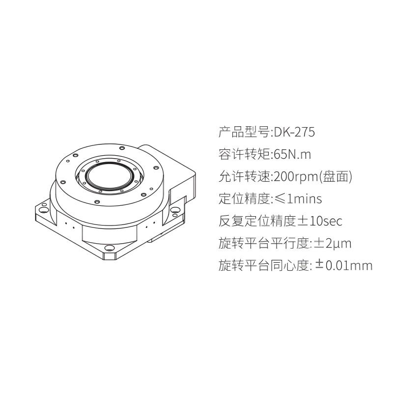
参数名称 | DK-60 | DK-100 | DK-130 | DK-200 | DK-275 | |||||
Modle | 42 型步进马达 | 100W Ac 伺服马达 | 60型步进马达 | 200-400W Ac 伺服马达 | 60型步进马达 | 200 - 400W Ac伺服马达 | 85型步进马达 | 750WAc伺服马达 | 85型步进马达 | 750WAc伺服马达 |
旋转平台轴承 | 深满滚珠轴承 + 止推滚珠轴承 | 圆锥滚珠轴承 | ||||||||
容许转矩 | 3.5N.m | 20N.m | 20N.m | 65N.m | 65N.m | |||||
惯性惯量 | 2330x10⁻⁷ kg.m² | 3898x10⁻⁶ kg.m² | 9216x10⁻⁶ kg.m² | 85792x10⁻⁶ kg.m² | 111279x10⁻⁶ kg.m² | |||||
允许转速 | 300rpm | 200rpm | 200rpm | 200rpm | 200rpm | 200rpm | ||||
解析度 P/R | 半步进设定~微步进设定 5000 - 600000 | 以伺服马达规格 | 半步进设定~微步进设定 8000 - 1500000 | 以伺服马达规格 | 半步进设定~微步进设定 8000 - 1500000 | 以伺服马达规格 | 半步进设定~微步进设定 10000 - 180000 | 以伺服马达规格 | 半步进设定~微步进设定 10000 - 1800000 | 以伺服马达规格 |
减速比 | 直结式减速机 1:5,1:20 | 直角减速机 1:10 | 直结式减速机 1:8 | 直角减速机 1:16 | 直结式减速机 1:10 | 直角减速机 1:20 | 直结式减速机 1:10 | 直角减速机 1:20,1:30 | 直结式减速机 1:10 | 直角减速机 1:20,1:30 |
定位精度 | ≤1mins | |||||||||
反复定位精度 | ±10sec | ±5sec | ±5sec | ±5sec | ±5sec | |||||
容许推力载量 | 20kgf | 200kgf | 250kgf | 500kgf | 800kgf | |||||
容许惯性载量 | 5N.m | 10N.m | 60N.m | 60N.m | 200N.m | 200N.m | ||||
旋转平台平行度 | ±5μm | ±2μm | ±2μm | ±2μm | ±2μm | |||||
旋转平台同心度 | ±0.01mm | ±0.01mm | ±0.01mm | ±0.01mm | ±0.01mm | |||||
保护等级 | 40IP | |||||||||
重量 | 2.2kg | 3kg | 5.5kg | 14kg | 19kg | |||||
性能介绍
PS圆周单位:1rpm=360°/1°=60'1'=60"
圆周误差换算直线误差:盘面直径x3.14159÷(360°x60'x60”)x精度误差
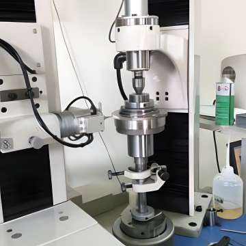
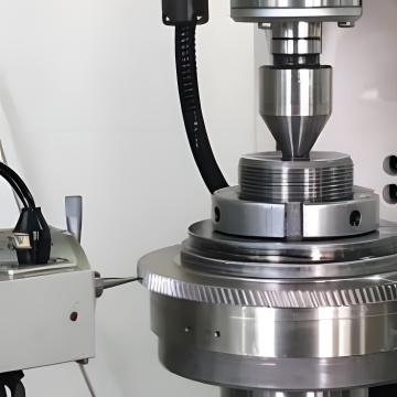
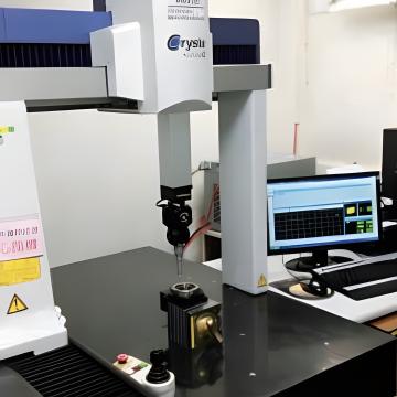
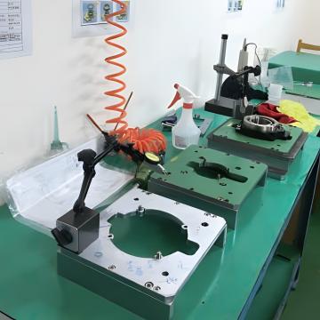
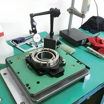
检验设备:系统化管理,定期效验以确保测量精度与追溯性
马达安装说明
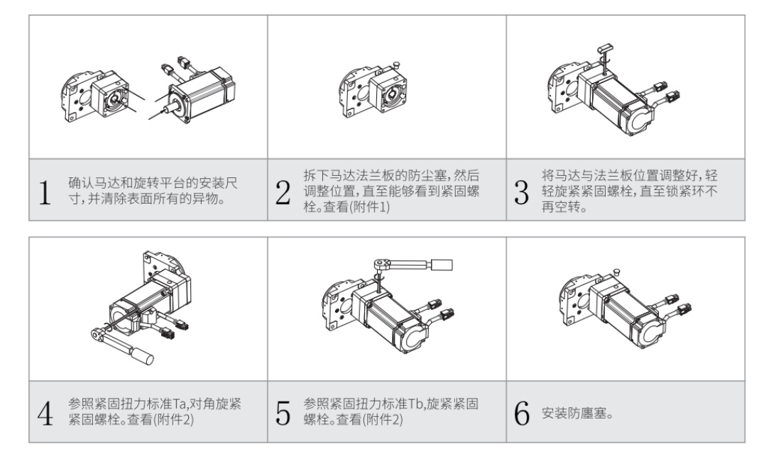
附件1:
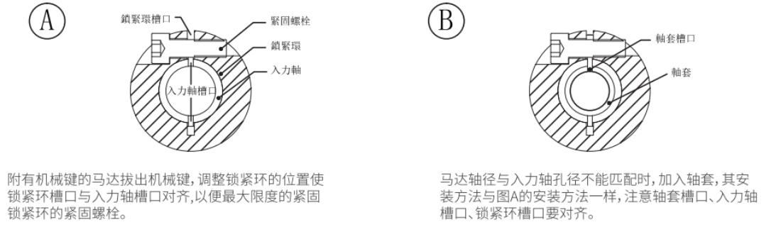
附件2:
扳手螺栓尺寸 | 马达安装 Ta-8.8T | 锁紧环安装Tb-12.9T | ||
(N.m) | (kgf.cm) | (N.m) | (kgf.cm) | |
M3 | 1.28 | 13 | 2.15 | 22 |
M4 | 2.9 | 30 | 4.95 | 50 |
M5 | 5.75 | 59 | 9.7 | 99 |
M6 | 9.9 | 101 | 16.5 | 168 |
M8 | 24 | 245 | 40 | 408 |
M10 | 48 | 489 | 81 | 826 |
M12 | 83 | 846 | 140 | 1428 |
M14 | 132 | 1346 | 220 | 2243 |
M16 | 200 | 2039 | 340 | 3467 |
平台安装说明
中空旋转平台安装说明
在中空旋转平台安装板上预留马达出口,以免马达与安装板干涉。
安装2个定位销孔将中空旋转平台定位,再对角旋紧紧固螺栓。
中空旋转平台上安装负载
中空旋转平台2个负载的定位销孔,用于确认负载的位置。
将负载安装在中空旋转平台安装面,使用.上面的6个螺纹孔完成对负载的紧定。
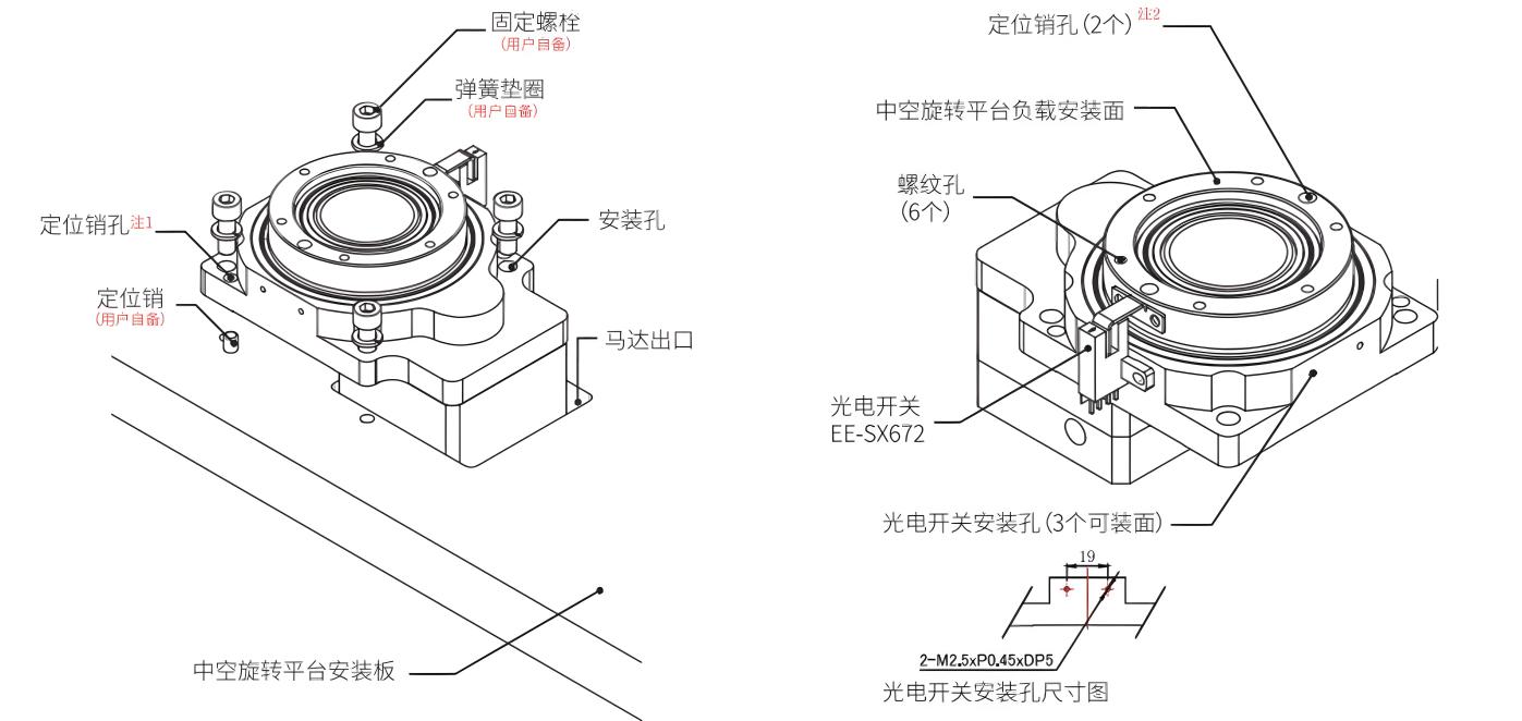
定位销孔尺寸(注1):
平台规格 | 销孔直径 mm | 销孔深度 mm | 销孔数量 |
DH60 | Ø5+0.0120(H7) | 10 (贯穿) | 2 |
DH85 | Ø5+0.0120(H7) | 10.5 (贯穿) | 2 |
DH130 | Ø5+0.0120(H7) | 11.5 (贯穿) | 2 |
DH200 | Ø5+0.0120(H7) | 15.2 (贯穿) | 2 |
定位销孔尺寸(注2):
平台规格 | 销孔直径 mm | 销孔深度 mm | 销孔数量 |
DH60 | Ø5+0.0120(H7) | 6 | 2 |
DH85 | Ø5+0.0120(H7) | 6 | 2 |
DH130 | Ø5+0.0120(H7) | 6 | 2 |
DH200 | Ø5+0.0120(H7) | 15 | 2 |
DH275 | Ø5+0.0120(H7) | 8 | 2 |
安装注意事项:
安装之前,应通读如下安装注意事项,并按照如下条件安装:
1. 室内(不直接接触阳光的区域)
2. 没有热辐射的区域
3.工作环境(温度:0~+50°℃/湿度:低于85%)
4.原点感测器下方温度:0+40°C
5.不存在易燃易爆的酸性气体
6.可阻挡灰尘、油和溅水的地方
7.不遭受直接震动和过度撞击的地方
选型计算
1. 计算搬运的转动惯量(负载转动惯量)
搬运物的转动惯量请以传动装置转动惯量 30 倍以下为标准。
2. 使用以下公式计算加速转矩
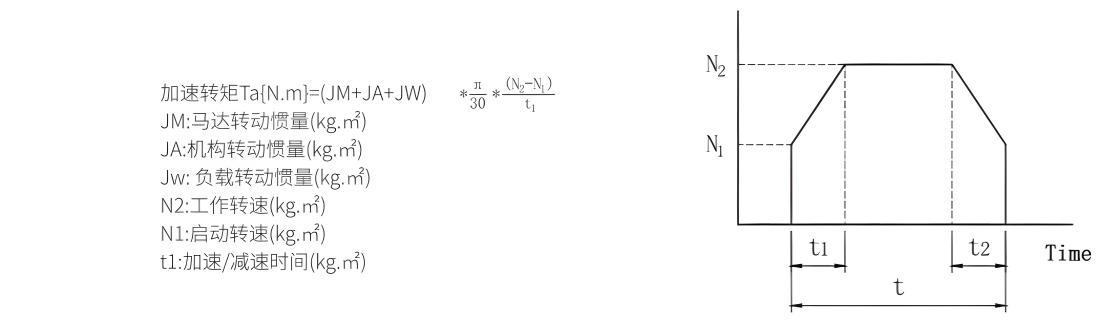
3. 计算所需转矩
所需的转矩是通过摩擦扭矩引起的负载转矩与由惯量引起的加速转矩相加之和乘以安全系数计算得出的。 所需转矩T=(负载转矩 (N.m)+ 加速转矩 (N.m))×S
安全系数S大于 1.5。
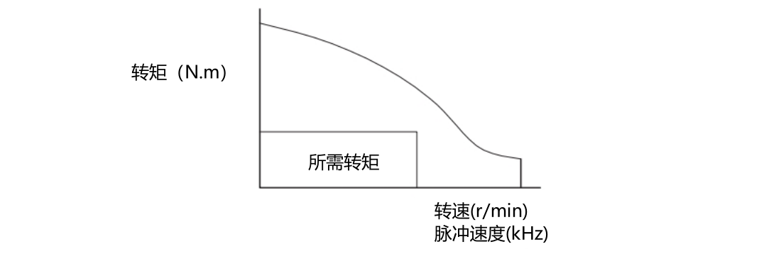
4. 选定马达所需的转矩 T 必须处于转速 - 转矩的规格范围内。
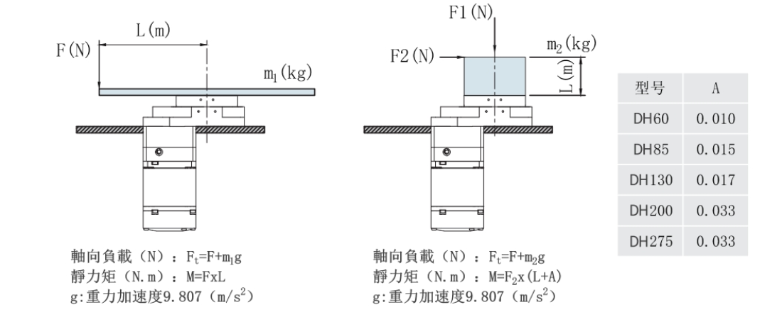
5. 轴向负载,静力矩的计算
在中空旋转平台上按照如下图所示施加负载时,请确保采用以下计算公式计算得出轴向负载和静力矩处于规定范围内。
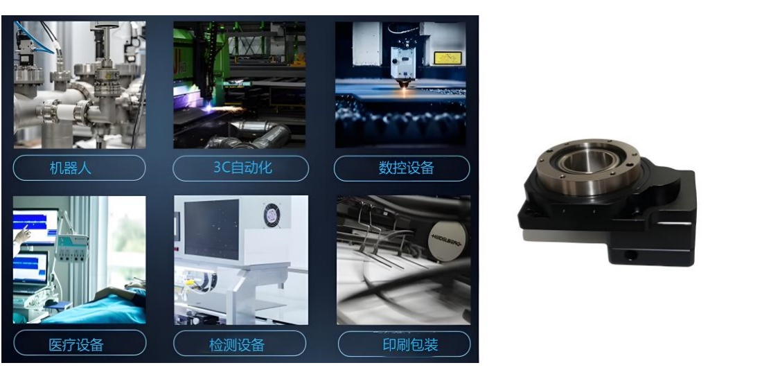
应用
机器人:用于机器人关节,提供灵活精准转动,如焊接、喷涂机器人,凭借中空结构方便管线穿行,避免线路干扰,提升动作流畅度与准确性。
3C 自动化:在 3C 产品制造中,实现电路板等元件精准旋转,便于焊接、贴片等操作,也用于检测环节,调整元件角度全方位检测,提高生产质量。
数控设备:充当数控机床第四轴,实现刀具库快速定位,助力复杂模具加工时刀具迅速切换,提高加工精度与表面质量,缩短辅助时间。
医疗设备:在 CT 等影像设备中带动部件旋转,获取多角度图像;用于手术机器人,实现精细手术操作,凭借高精度保障医疗检测与手术的准确性。
检测设备:带动光学镜片、电子元件等被检测物件多角度旋转,配合检测仪器,实现全方位高精度测量,确保检测结果准确可靠。
印刷包装:在印刷机中保证印版滚筒精准旋转,实现图案准确套印;在贴标机里控制产品旋转,让标签精准贴附,提升包装印刷品质 。
产品保障
产品设计与研发:中控旋转平台在设计阶段,汇聚专业工程师团队,运用先进的计算机辅助设计(CAD)与模拟分析软件,对产品结构、动力传输、控制逻辑等核心部分进行精细化模拟和优化,确保从源头保障产品性能的可靠性与稳定性。所有设计方案需历经多轮内部评审与测试验证,通过后方可进入生产环节。
原材料采购:严格筛选原材料供应商,建立长期稳定且高标准的合作关系。针对每一批次的原材料,均进行严格的质量检测,涵盖金属材料的成分分析、机械性能测试,电子元件的电气参数检测、可靠性测试等。只有符合或超越行业标准的原材料,才会被允许投入生产,以此确保产品基础质量。
生产过程管控:生产车间遵循严格的质量管理体系运作,引入自动化生产设备与高精度检测仪器,实现生产流程的标准化、精细化。在生产的各个关键节点,设置质量检测点,对半成品进行实时抽检与全检,包括零部件加工精度检测、装配质量检测、电气性能初测等。对生产过程中出现的质量问题,立即启动追溯与整改机制,确保问题产品不流入下一环节。
成品检验:每一台中控旋转平台在出厂前,都要经过全面且严苛的成品检验流程。检验项目包括但不限于空载运行测试、满载运行测试、定位精度测试、重复定位精度测试、噪声与振动测试、电气安全性能测试等。只有各项指标完全符合产品质量标准的设备,才会被贴上合格标签,准予出厂。
售后保障
如产品出现故障,我们的售后团队会在第一时间响应,迅速安排专业技术人员与您沟通,了解故障详情。我们会根据具体情况,为您提供远程技术指导,协助您解决问题。同时,我们还为您提供定期回访服务,了解产品的使用情况,收集您的意见和建议,以便不断优化产品和服务。在产品升级换代时,我们也会及时通知您,为您提供相应的技术支持和解决方案,让您的设备始终保持良好性能。