Product Description
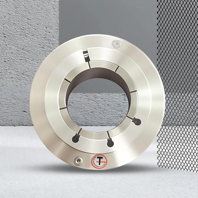
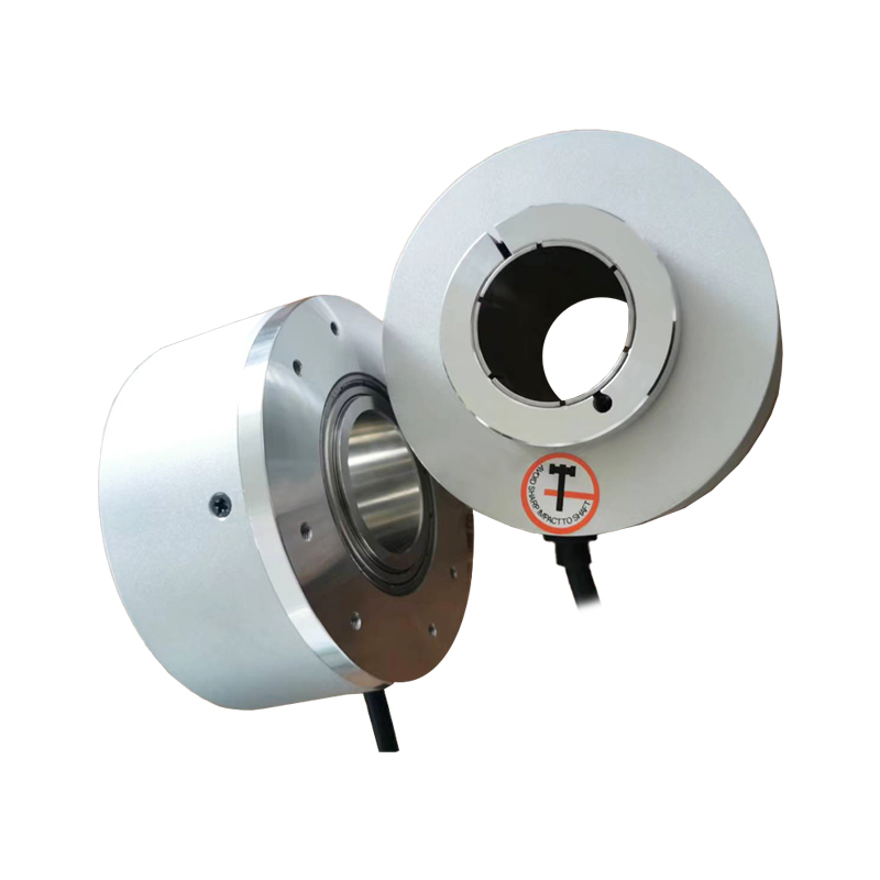
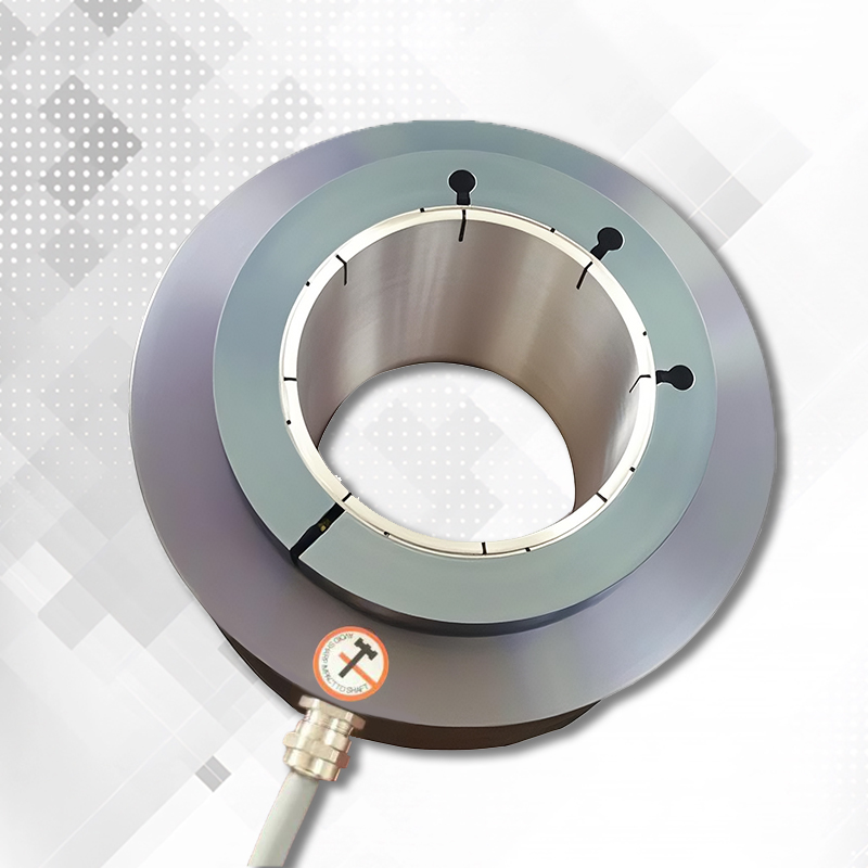
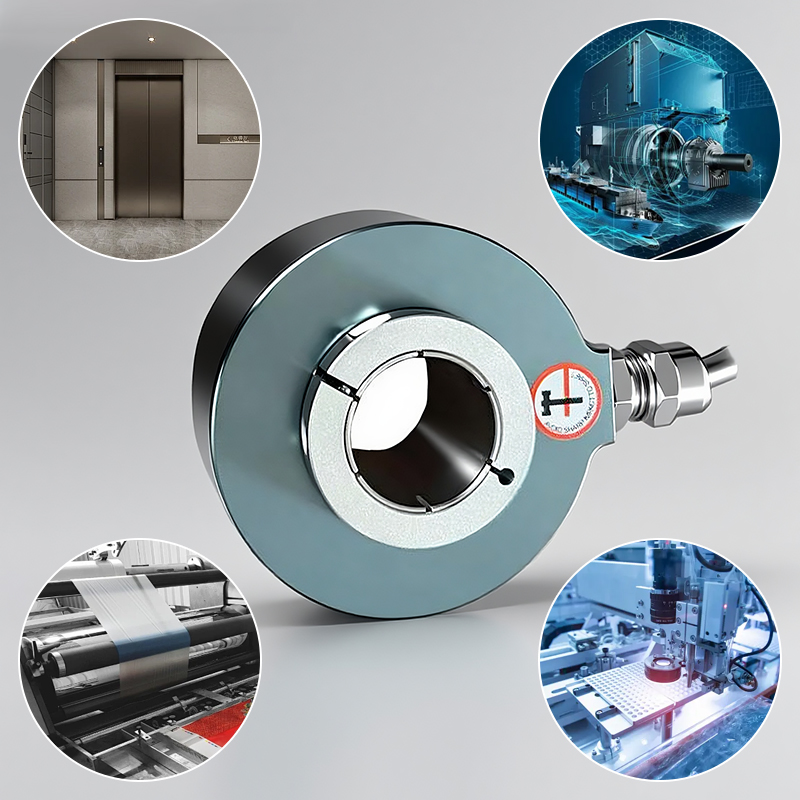
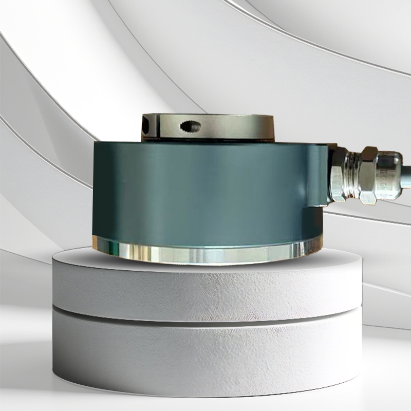
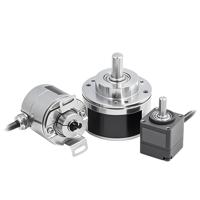
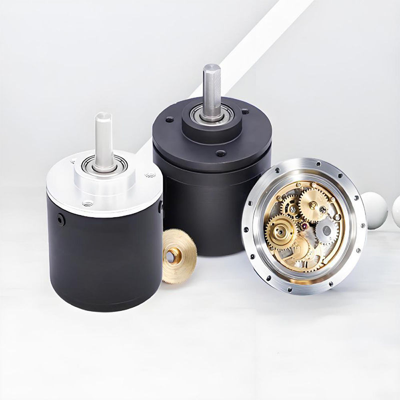
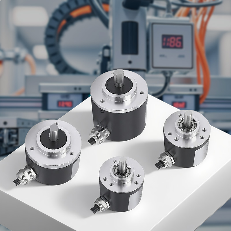
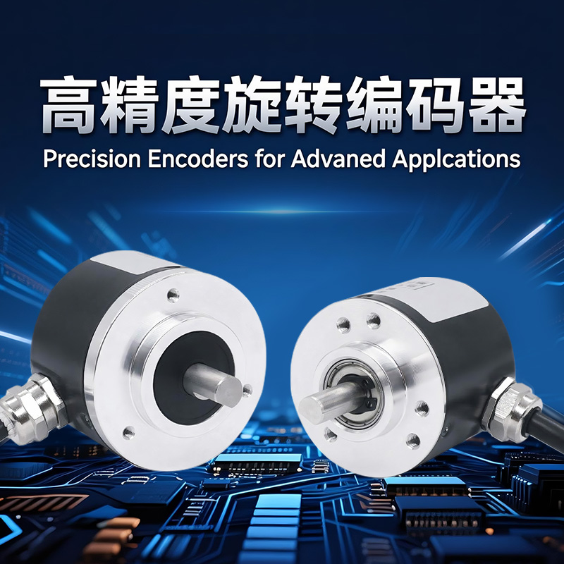
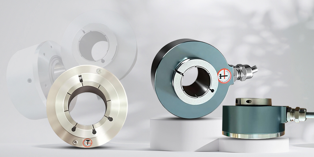
MK series conventional incremental through-hole encoders use ASIC components, with stable performance, long life, and strong anti-interference. Covering different sizes and parameters, it is suitable for multiple scenarios such as automation control, measurement, and motors, helping equipment to operate accurately.
Product parameters
MK44
Designate the name of funtion when ordering
MK44 | 12 | G | 200 | B | M | - | L | 5 | · | |||||||
↑ | ↑ | ↑ | ↑ | ↑ | ↑ | ↑ | ↑ | ↑ | ||||||||
Shell size | Output shaft | Cable outlet | Resolution P/R | Output phase | Zero signal | Output mode | Working voltage | Special Code | ||||||||
Ø44mm | 08=Ø8mm | C = socket outlet | A = single-phase output A | S=No Z signal | T=voltage type output NPN+R | 5=+5V | ||||||||||
10=Ø10mm | G = cable outlet on the side | B = 2-phase output A, B | M=Z signal output "1" | C=NPN open collector | 526= +5~+26V | |||||||||||
12=Ø12mm | H = socket outlet at the back | N=Z signal output "0" | CP=PNP open collector | |||||||||||||
E = cable outlet at the back | P=complementary circuit PNP+NPN | |||||||||||||||
J = computer socket outlet on the side - pin | L=long line driver (26LS31) | |||||||||||||||
T = computer socket outlet at the back - pin | K=long line driver (7272) | |||||||||||||||
V=long line drive differential OC (7273) |
Wiring table
Signal | A | B | Z | `A | `B | `Z | Vcc | GND |
Color | Green | White | Yellow | Brown | Gray | Orange | Red | Black |
Electrical specifications
Output circuit | Open collector output | Voltage output | Complementary output | Long-line drive output |
Power supply voltage Vcc | 5~26 | 5±0.25, 5~26 | ||
Current consumption | ≤80mA | ≤150mA | ||
Load current | 40mA | 60mA | ||
Output H high level | Minimum Vcc*70% | Minimum Vcc - 2.5V | Minimum Vcc - 1.5V | Minimum 3.4V |
Output low high level | Maximum 0.4V | Maximum 0.8V | Maximum 0.4V | |
Rise time Tr | MAX 1us | MAX 200ns | ||
Fall time Tf | MAX 1us | MAX 200ns | ||
Maximum frequency response | 300kHz | |||
Maximum speed per minute r/min | Starting torque | Maximum shaft load | Shock resistance | Vibration resistance |
6000 | <0.05Nm | Radial 50N, axial 20N | 50G/11ms | 10G, 10 - 2000Hz |
Moment of inertia | Operating temperature | Storage temperature | Protection level | Weight |
4×10⁻8kg·m² | -30~85℃ | -35~95℃ | IP51 | 100g |

MK80
Designate the name of funtion when ordering
Mk80 | 30 | J | - | 1021 | B | M | - | L | 5 | · | ||||||
↑ | ↑ | ↑ | ↑ | ↑ | ↑ | ↑ | ↑ | ↑ | ||||||||
Shell size | Output shaft | Cable outlet | Resolution P/R | Output phase | Zero signal | Output mode | Working voltage | Special Code | ||||||||
Ø80mm | 18=Ø18mm | C = socket outlet | A = single-phase output A | S=No Z signal | T=voltage type output NPN+R | 5=+5V | ||||||||||
20=Ø20mm | G = cable outlet on the side | B = 2-phase output A, B | M=Z signal output "1" | C=NPN open collector | 526= +5~+26V | |||||||||||
30=Ø30mm | H = socket outlet at the back | N=Z signal output "0" | CP=PNP open collector | |||||||||||||
E = cable outlet at the back | P=complementary circuit PNP+NPN | |||||||||||||||
J = computer socket outlet on the side - pin | L=long line driver (26LS31) | |||||||||||||||
T = computer socket outlet at the back - pin | K=long line driver (7272) | |||||||||||||||
V=long line drive differential OC (7273) |
Signal | A | B | Z | `A | `B | `Z | Vcc | GND | Shielding |
Color | Green | White | Yellow | Brown | Gray | Orange | Red | Black | Copper mesh |
DB15 plug | 4 | 2 | 9 | — | — | — | 7 | 5 | 8 |
DB15 plug | 5 | 3 | 2 | 7 | 6 | 8 | 1 | 4 | 9 |
Output circuit | Open collector output | Voltage output | Complementary output | Long-line drive output |
Power supply voltage Vcc | 5~26 | 5±0.25, 5~26 | ||
Current consumption | ≤80mA | ≤150mA | ||
Load current | 40mA | 60mA | ||
Output H high level | Minimum Vcc*70% | Minimum Vcc - 2.5V | Minimum Vcc - 1.5V | Minimum 3.4V |
Output low high level | Maximum 0.4V | Maximum 0.8V | Maximum 0.4V | |
Rise time Tr | MAX 1us | MAX 200ns | ||
Fall time Tf | MAX 1us | MAX 200ns | ||
Maximum frequency response | 300kHz | |||
Maximum speed per minute r/min | Starting torque | Maximum shaft load | Shock resistance | Vibration resistance |
5000 | <1Nm | Radial 20N, axial 10N | 50G/11ms | 10G、10 - 2000Hz |
Moment of inertia | Operating temperature | Storage temperature | Protection level | Weight |
4×10⁻8kg·m² | -30~85℃ | -35~95℃ | IP50 | 400g |
Dimension(Unit: mm)

Product Display
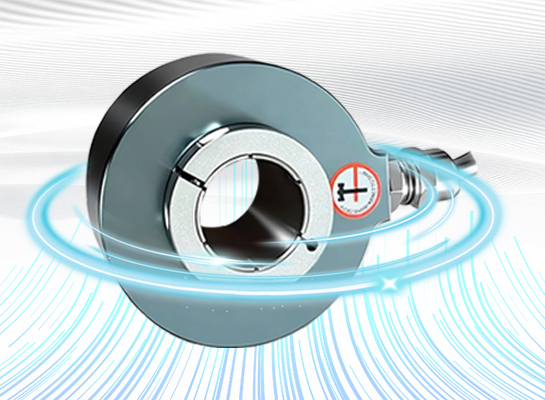
Through-hole design: hollow shaft structure, suitable for a variety of shaft diameters, easy to install
High resolution: provides 100-10000PPR optional pulse number, positioning accuracy ±0.01°
Strong anti-interference: built-in ASIC chip, anti-electromagnetic interference up to 10V/m (10-1000MHz)
Durable and reliable: average trouble-free operation of 50,000 hours, protection level IP65
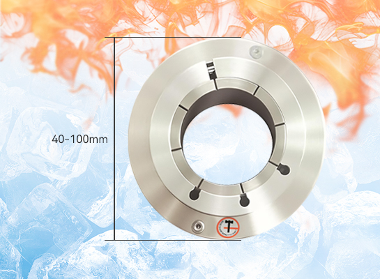
Wide operating temperature: -20℃~85℃ temperature range, adaptable to harsh industrial environments
Multi-signal output: supports TTL/HTL push-pull output, response frequency ≤200kHz
Compact structure: outer diameter 40-100mm optional, saving installation space
Anti-vibration and anti-shake: anti-vibration 20g (10-2000Hz), anti-shock 100g (6ms)
Quality Control
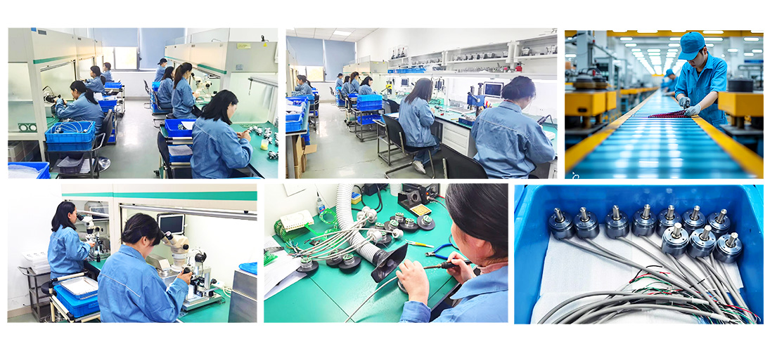
The quality of encoders is directly related to the stability and reliability of industrial automation systems. We have built a full-process quality control system, strictly screening suppliers from raw material procurement to ensure that the performance of core components meets standards; in the production process, we use high-precision equipment and standardized processes, and cooperate with online detection technology for real-time monitoring; in the finished product stage, we conduct rigorous tests such as high and low temperature, electromagnetic compatibility, and life aging to eliminate performance risks. Each encoder has passed multiple quality inspection levels, and its excellent quality has laid a solid foundation for intelligent manufacturing, providing customers with long-term and stable use guarantees.
Application Cases
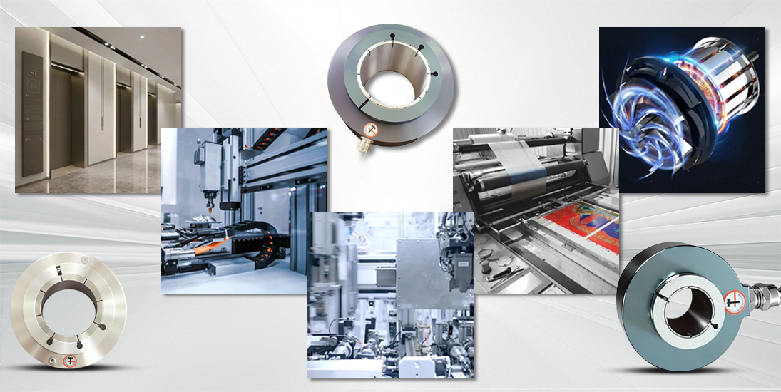
MK series incremental through-hole encoders, with their stable performance, are suitable for automation control and measurement scenarios, such as precise positioning of robot X-Y worktables; they are also used in printing and packaging, elevators, and motor equipment to assist in speed monitoring and position feedback to ensure operating accuracy.
