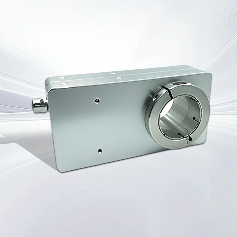
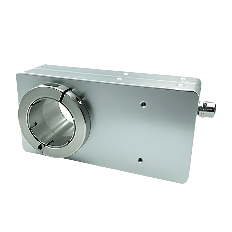
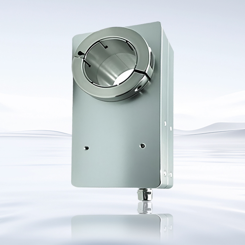
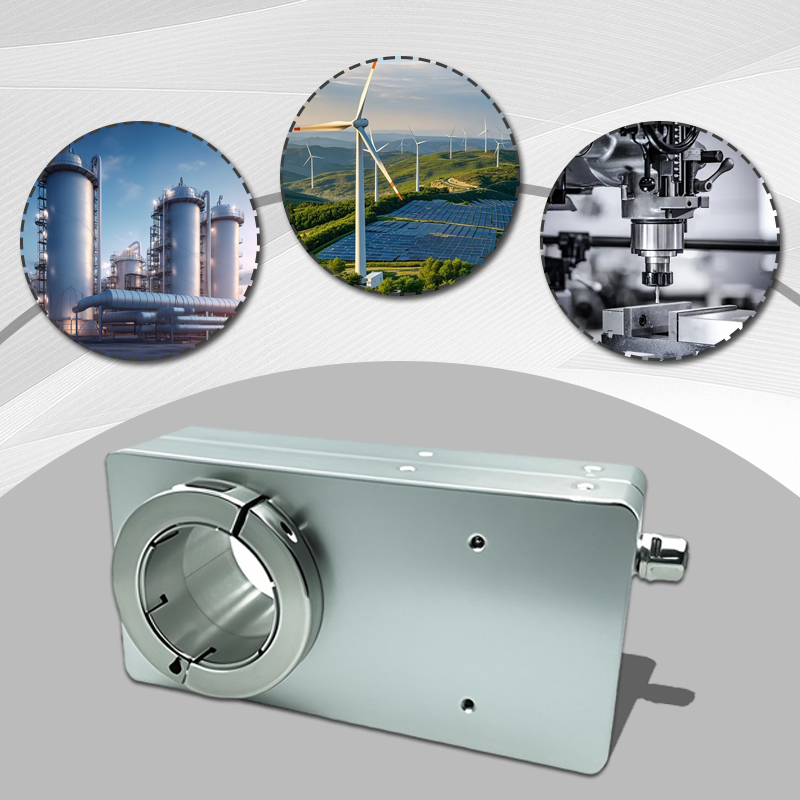
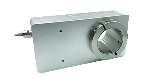
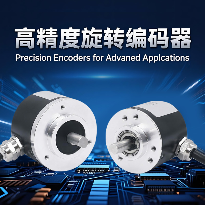
Product Description
◆ Any output signal is optional, universal through-hole absolute value encoder |
|
Product parameters
Product series | BAAT80 |
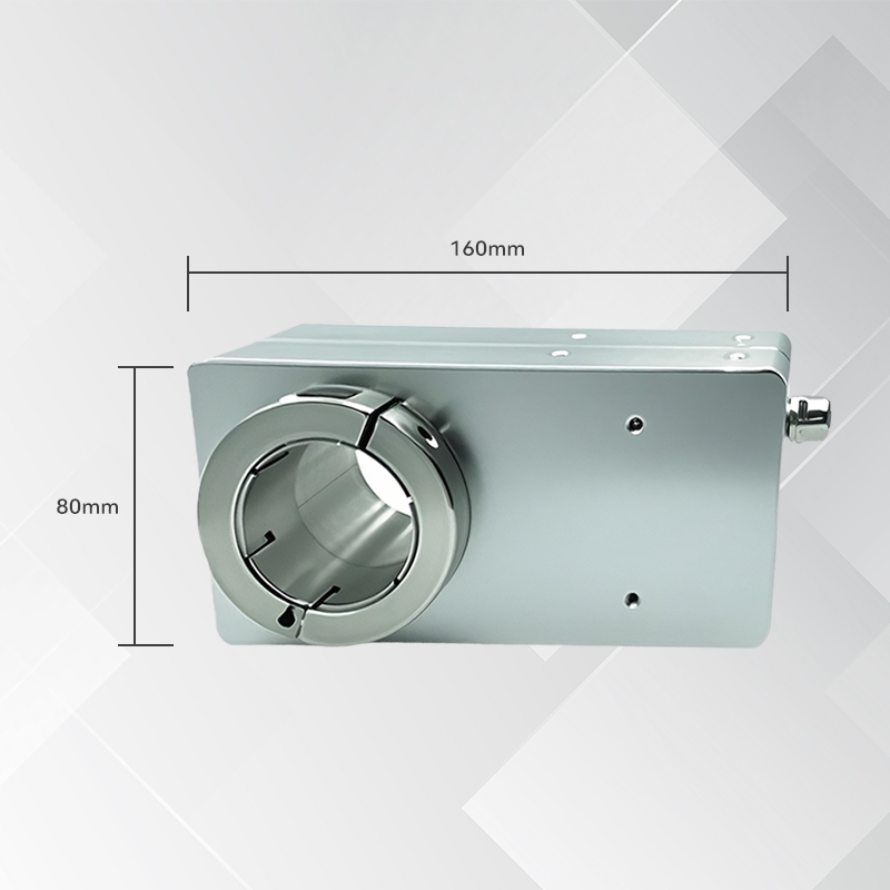
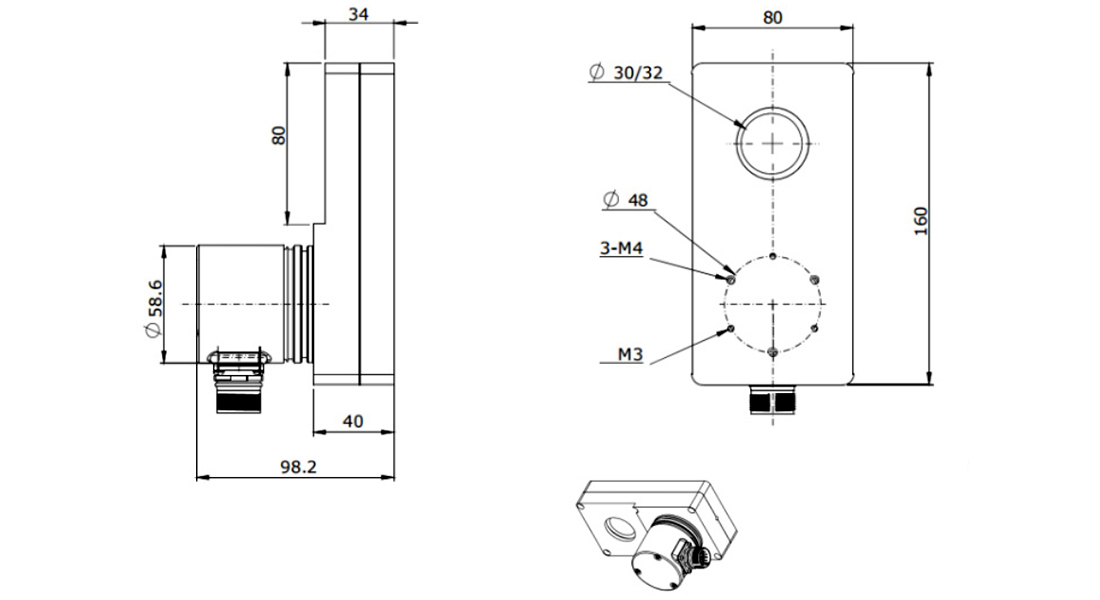
Size (Shell) | 80X160mm |
Characteristics | Through-hole type |
Spindle size | Through-hole type 18... 50mm |
Output signal | Optional analog quantities: 4-20mA,0-5V,0-10V,0-20mA, digital quantities: RS485, Modbus, SSI, parallel, CANopen, Profibus-DP, ProfiNet/IO, etc. (Angle, length, speed application output can be set.) |
Power supply voltage | 10... 30VDC or 5VDC(reverse polarity protection, overvoltage protection) |
Single-circle resolution | Standard 12-bit 40960 line (maximum 16-bit 65536) |
Number of rotations | One lap, 12 positions, 4096 laps |
Repetition accuracy | ±2BIT |
Consumed current | <30mA(24V power supply) no-load |
Signal adjustment | The corresponding value for each circle is adjustable, the direction is adjustable, the preset position is adjustable, the external zero position is adjustable, the baud rate is adjustable, and the address is adjustable |
Maximum rotational speed | 3000r/min |
Main shaft load | Radial: 80N, axial: 40N |
Protection grade | IP65 |
Starting torque | ≤3Ncm |
Working temperature | - 30... 85℃(Customizable working temperature -40°...) 85 ℃) |
Storage temperature | - 40... 100 ℃ |
Impact-resistant | 1000m/s²,6ms(100g) |
Anti-vibration | 20g |
Connection method | 8-core shielded cable or aviation plug |
Qualification method | The radial side protrudes and the shaft protrudes backward |
485 analog wiring table | Parallel encoder wiring | |||||||||||||||
Color | brown | white | pink | black | green | yellow | blue | Grey | Signal | 26-pin terminal | Color line | Signal | 26-pin terminal | Color line | ||
Signal | Vcc | 0V | Analog quantity + | Analog quantity - | RS485A | RS485B | Set Allow | External zeroing | Bit 1 | Pin 1 | white | Bit 16 | Pin 16 | Yellow - brown | ||
Bit 2 | 2 | brown | Bit 17 | 17 | White - Grey | |||||||||||
CANopen wiring | Profibus-DP wiring table | Bit 3 | 3 | green | Bit 18 | 18 | Grey - brown | |||||||||
Function number | Description | Fixture | Description | Bit 4 | 4 | yellow | Bit 19 | 19 | White - pink | |||||||
⊥ | Grounding | B(left) | Bus B(Bus Input) | Bit 5 | 5 | grey | Bit 20 | 20 | Pink - brown | |||||||
+ | 0... 30V power supply | A (left) | Bus A(Bus Input) | Bit 6 | 6 | powder | Bit 21 | 21 | White - Blue | |||||||
- | 0V power supply | - | 0V | Bit 7 | 7 | blue | Bit 22 | - | Brownish blue | |||||||
G左 | CAN ground (bus input) | + | 10-30V | Bit 8 | 8 | red | Bit 23 | - | White - Red | |||||||
L左 | CAN low (bus input) | B(right) | Bus B(Bus Exit) | Bit 9 | 9 | black | Bit 24 | - | Brownish red | |||||||
H左 | CAN high (bus input | A(right) | Bus A(Bus Exit) | Bit 10 | 10 | The purple | Bit 25 | 0 | White and black | |||||||
G右 | CAN ground (bus output) | - | 0V | Bit 11 | 11 | Grey powder | Pre-settings | 22 | Brownish black | |||||||
L右 | CAN low (bus output) | + | 10-30V | Bit 12 | 12 | Blue - Red | Locked | 23 | Grey - Green | |||||||
H右 | CAN high (bus output) | Bit 13 | 13 | White and green | Direction code | 24 | Yellow - Grey | |||||||||
Bit 14 | 14 | Brownish green | +Uo=10-30V | 25 | Pink - green | |||||||||||
Bit 15 | Pin 15 | White and yellow | to | Pin 26 | Yellow - pink | |||||||||||
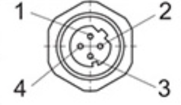
Ethernet Data Port 1 | Color pins | Brown 2 | White 1 | green 3 | Yellow 4 | Grey 5 | Pink 6 | Black 9 | Blue 8 | |||||||
Signal | TXD+ | RXD+ | TXD- | RXD- |
| Signal | Vcc | OV | CLOCK+ | CLOCK- | DATA+ | DATA- | Reset to zero | Rotation direction | ||
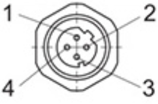
Needle number | 1 | 2 | 3 | 4 | Signal | Vcc | OV | CLOCK+ | CLOCK- | DATA+ | DATA- | Reset to zero | Rotation direction | |||
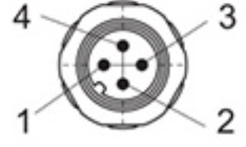
Power interface | ||||||||||||||||
Signal | +V | —— | OV | —— |
| |||||||||||
Needle number | 1 | —— | 3 | —— | ||||||||||||
Data port 2 | ||||||||||||||||
Signal | TXD+ | RXD+ | TXD- | RXD- |
| |||||||||||
Needle number | 1 | 2 | 3 | 4 | ||||||||||||
Order model code: | 1 | 2 | 3 | 4 | 5 | 6 | 7 | 8 | 9 | |||
Absolute value encoder | BAAT80 | - | XXX | XXX | XX | -XXX | X | -X | XX | -XX | ||
1. Specification series | ||||||||||||
BAAT80 | - | |||||||||||
2. Output signal | ||||||||||||
RL1 4-20mA | RL1 | |||||||||||
RV0 0-10V | RV0 | |||||||||||
RV5 0-5V | RV5 | |||||||||||
RL0 0-20mA | RL0 | |||||||||||
R4 RS485 输出 | R4 | |||||||||||
RM Modbus Output | RM | |||||||||||
SG SSI Output | SG | |||||||||||
PB Parallel output | PB | |||||||||||
CA CANopen Output | CA | |||||||||||
PN ProfiNet Output | PN | |||||||||||
DP Profibus-DP Output | DP | |||||||||||
3. Number of rotations | ||||||||||||
B01 One lap (single lap) | B01 | |||||||||||
B12 12bit 4096 laps (multiple laps) | B12 | |||||||||||
4. Resolution per circle | ||||||||||||
12 12 bit(4096 resolution) standard product | 12 | |||||||||||
13 13 bit(8192 Resolution) | 13 | |||||||||||
14 14 bit(16384 Resolution) | 14 | |||||||||||
16 16 bit(65536 Resolution) | 16 | |||||||||||
5. Mechanical installation dimensions | ||||||||||||
For details, please refer to the mechanical dimension drawing and order code of the encoder | ||||||||||||
6. Protection level, housing material | ||||||||||||
0 Protection grade IP65, aluminum alloy casing | 0 | |||||||||||
H Protection grade IP66, aluminum alloy shell (military-grade low-temperature standard -40°C) | H | |||||||||||
7. Qualification method | ||||||||||||
A The axis protrudes backward. | A | |||||||||||
R Radial lateral protrusion | R | |||||||||||
8. Connection form | ||||||||||||
A1 Cable Ø6.8mm, 8x2x0.35mm ², 1m (length customizable) | A1 | |||||||||||
AC 8-pin plug | AC | |||||||||||
AB 12-pin M23 plug | AB | |||||||||||
9. EX explosion-proof type | ||||||||||||
EX explosion-proof encoder EX II 2G Ex ib IIB T4 Gb | EX | |||||||||||
If there is no suitable product combination for your model and specification, you can also call us and we will customize the product for you | ||||||||||||
Installation dimension drawing
Product Display
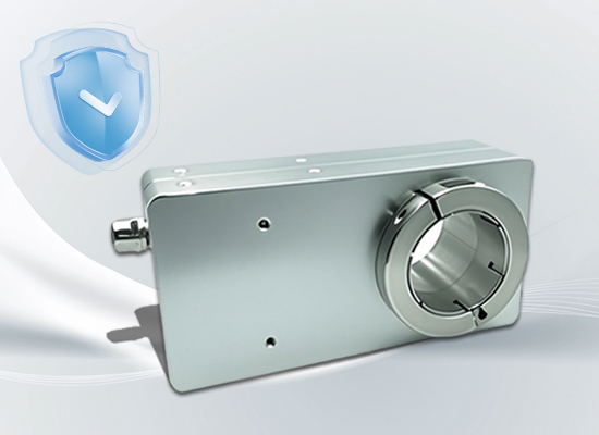
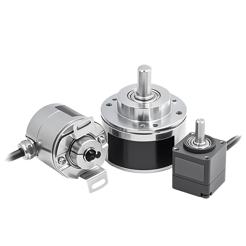
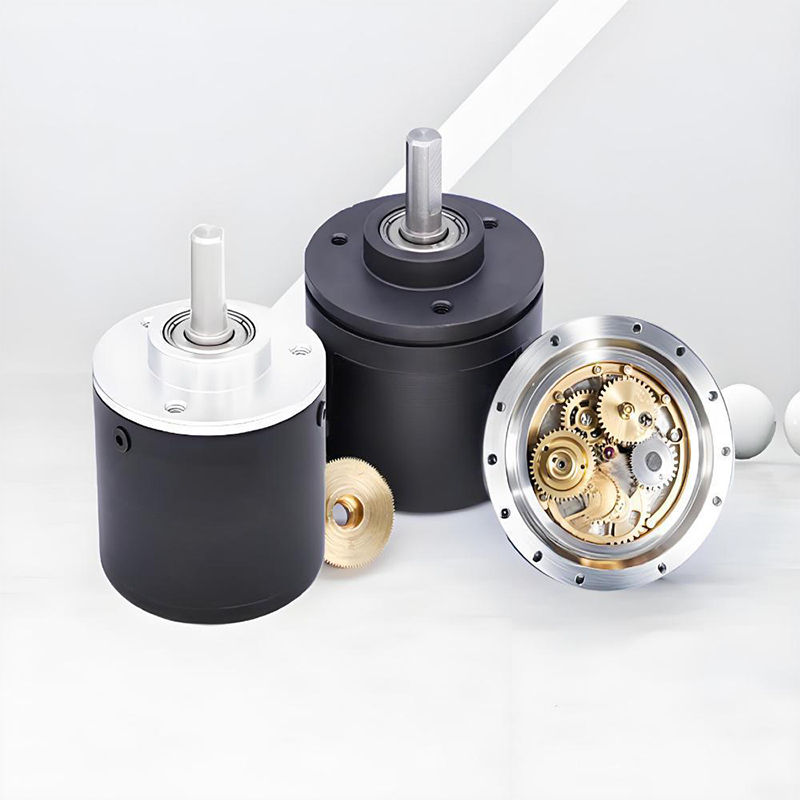
The absolute value of the large aperture is encoded. The super-large aperture is suitable for large shaft diameters and is easy to install
With the support of absolute value technology, the position after power failure and restart is precise
There is no risk of "lost turns" in multi-turn measurement, and stable output can be achieved even under harsh working conditions
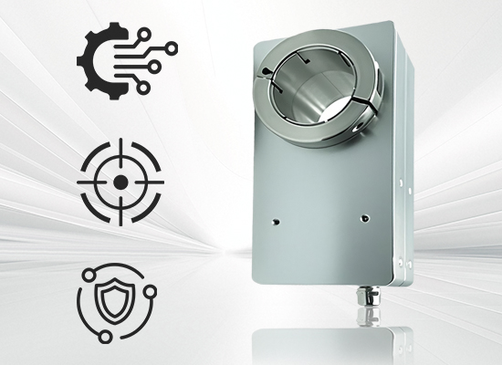
The large-aperture absolute value encoder features all-digital signal transmission and strong anti-interference ability
A variety of installation accessories can be flexibly matched with mechanical parameters
High precision and good stability lay a solid foundation for the efficient operation of the equipment
Application Cases
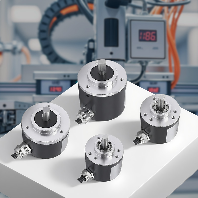
This product is involved in industries and projects such as ports, lifting, shipping, mining, water conservancy, steel and metallurgy, petrochemicals, stone, energy, food processing, aerospace, automobiles, papermaking and printing, injection molding, textiles, packaging, military industry, elevators, machine tools, etc.

Service
1. Precautions for Using Encoders
A place where the ambient temperature must not exceed the storage temperature; A place where the relative humidity must not exceed the storage
humidity; It cannot be in places with sharp temperature changes and fogging. Places close to corrosive gases and flammable gases; Stay away from
places with a lot of dust, salt and metal powder. Stay away from places where water, oil and medicine are used; Excessive vibration and shock can be
transmitted to the main body
2. Precautions for Installing Encoders
Electrical components must not be subjected to overvoltage or other phenomena. Please conduct static electricity assessment of the setting
environment, etc. Do not allow the motor power line to approach the encoder. The FG wire of the motor and the FG wire of the mechanical device
must be reliably grounded. Since the shielded wire is not connected to the encoder body, the shielded wire must be effectively connected to the
ground at the user end
3. Precautions on Wiring
When used at the specified power supply voltage, please pay attention to the decrease in power supply voltage amplitude caused by the long wiring.
Please do not use the encoder line and other power lines in the same pipe or bundle them in parallel. Please use twisted-pair wires for the signal line
and power line of the encoder. Please do not apply excessive force to the wire harness of the encoder, as there is a risk of wire breakage
4. Regarding the warranty of the encoder
Within twelve months of purchasing the products of our company, if any malfunction occurs due to correct use in accordance with the precautions
in the user manual, warning signs, etc., free warranty will be provided.
The following situations will be charged even within the warranty period: (Freight is at your own expense)
①. Faults and damages caused by the user landing during transportation or handling or improper installation;
②. Faults of this product caused by the machine connected to it;
③. Faults and damages caused by fire, salt water, corrosive gases, abnormal voltages, and other natural disasters such as earthquakes, lightning, wind, and floods;
④. Repair, adjustment or modification without the permission of our company (the label is not present or the outer cover is removed by oneself).
⑤. Malfunctions that occur when the user does not follow the usage methods and precautions described in the user manual.
⑥. Except where there are other agreements signed with the client.


