
Product Description
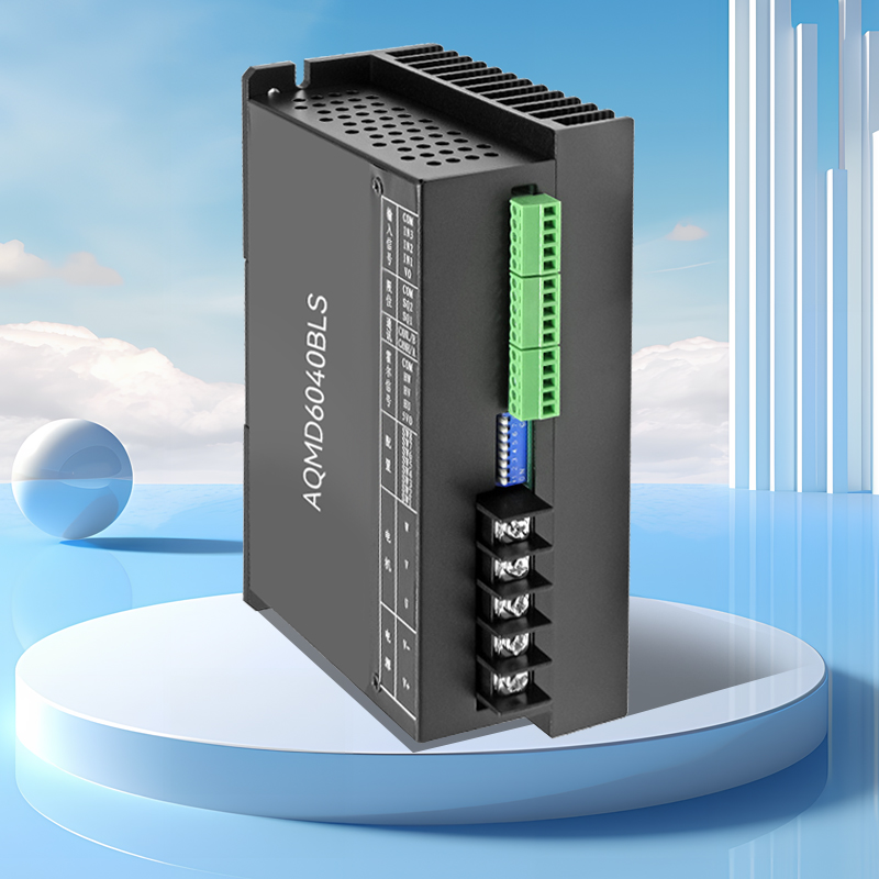
Model: AQMD6040BLS-E2F |
|
The AQMD_BLS series motor driver adopts advanced motor current precise detection technology, self-speed measurement of inductive brushless motors, rotational position detection of inductive brushless motors, regenerative current constant current braking and acceleration control technology, and PID regulation technology. It can perfectly control the smooth forward and reverse rotation, reversing and braking of the motor, and the output current is regulated in real time to prevent overcurrent. The motor speed and rotation position are precisely controlled, resulting in a short motor response time and small backlash force.
Functional features
● Automatic phase sequence adaptation of the motor
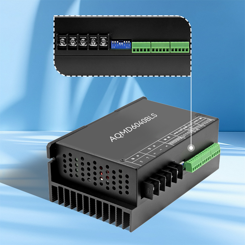
The three power lines or three Hall signal lines of the motor do not need to be connected to the driver in sequence. Just set the 4th and 5th positions of the dip switch to ON to learn the Hall sequence of the motor. The motor can be driven normally only after the learning is completed after six commutation controls of the motor.
●It is compatible with multiple control signals and various control methods
It supports multiple control signals such as potentiometer, analog quantity, PWM/ frequency/pulse, 485/CAN, and multiple working modes including motor open-loop speed regulation, closed-loop speed regulation, position control, and torque control.
● It can be started with a large torque for safe overload
Supports double current output, thereby achieving up to twice the rated torque start-up and twice the rated torque overload operation. The current doubling time can be set to prevent the motor from being damaged due to long-term overload operation. Meanwhile, the driver monitors the internal temperature in real time. When the temperature reaches the set value, it disables the current doubling or turns off the output to protect the driver.
● It has strong rigidity at extremely low speeds and stable speeds
The time-position closed-loop speed regulation algorithm of the driver enables the motor to have strong rigidity during low-speed operation and can also achieve high-torque closed-loop speed regulation control at a speed as low as 60RPM.
● High-speed positioning is precise and stable
The advanced position control algorithm of the driver can control the motor in accordance with Newton's laws of motion based on the given acceleration and maximum speed, ensuring precise and stable positioning even at high speeds.
● Four-quadrant operation control
It can control the motor to generate a torque opposite to the motor's rotation direction and perform acceleration control. Thus, whether in horizontal or vertical motion, closed-loop speed regulation and position control can be reliably controlled.
● Custom process control
For the control of conventional motion processes, the logical control of the motion process can be achieved through a custom process script, thereby eliminating the need for logic controllers like PLCS.
●Multiple protections ensure safety and reliability
Real-time monitoring of voltage, current and temperature, with multiple protections such as overheat, overcurrent, locked rotor, short circuit and static electricity, makes the driver work more stably and reliably.
Principle Overview
This driver employs advanced motor current precise detection technology, self-speed measurement for inductive brushless motors, and rotation position measurement for inductive brushless motors
The detection, regeneration current constant current braking (or braking) technology and the powerful PID regulation technology can perfectly control the motor to be stable
Forward and reverse rotation, reversing and braking, real-time regulation of output current to prevent overcurrent, precise control of motor speed and rotation position, and motor response
The time is short and the recoil force is small.
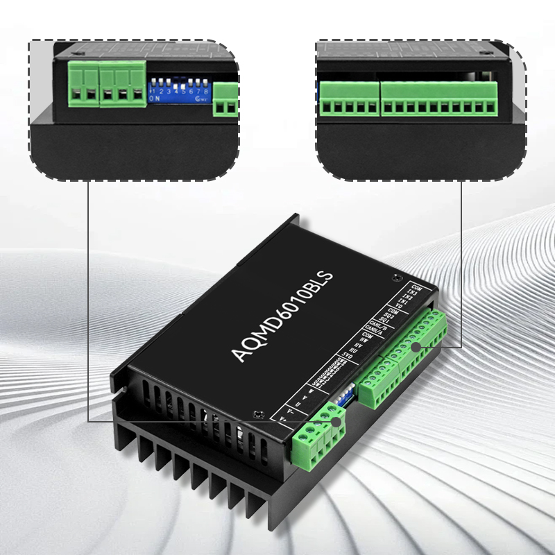
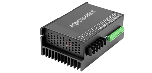
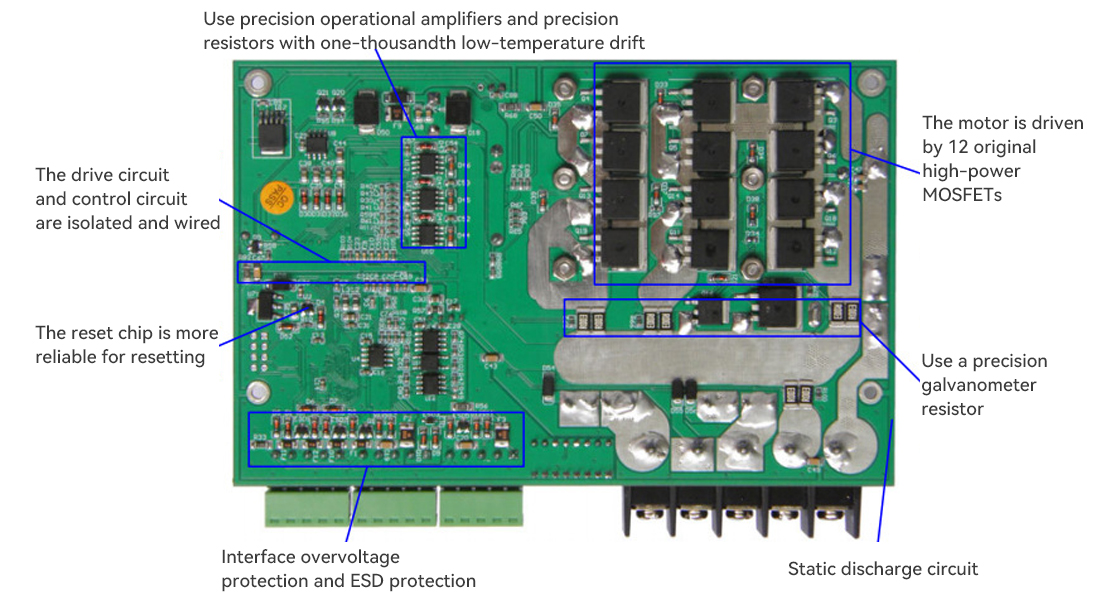
Front of the drive
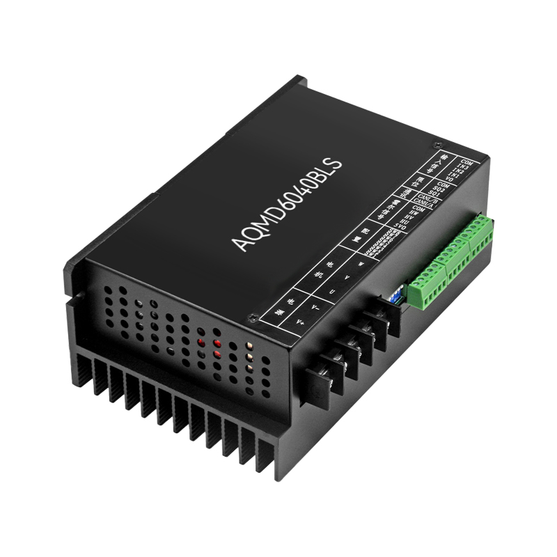
Back of the drive
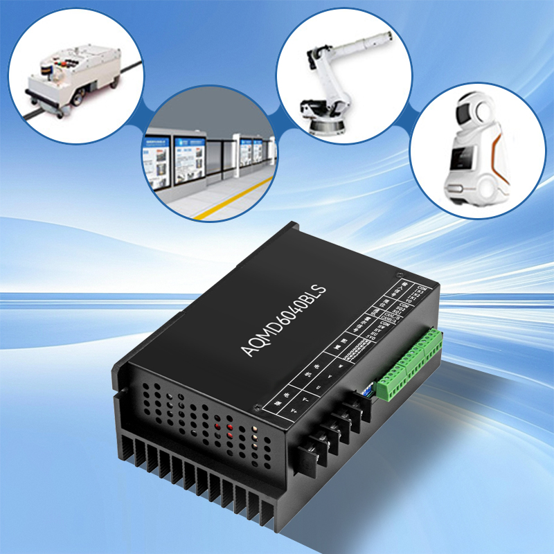
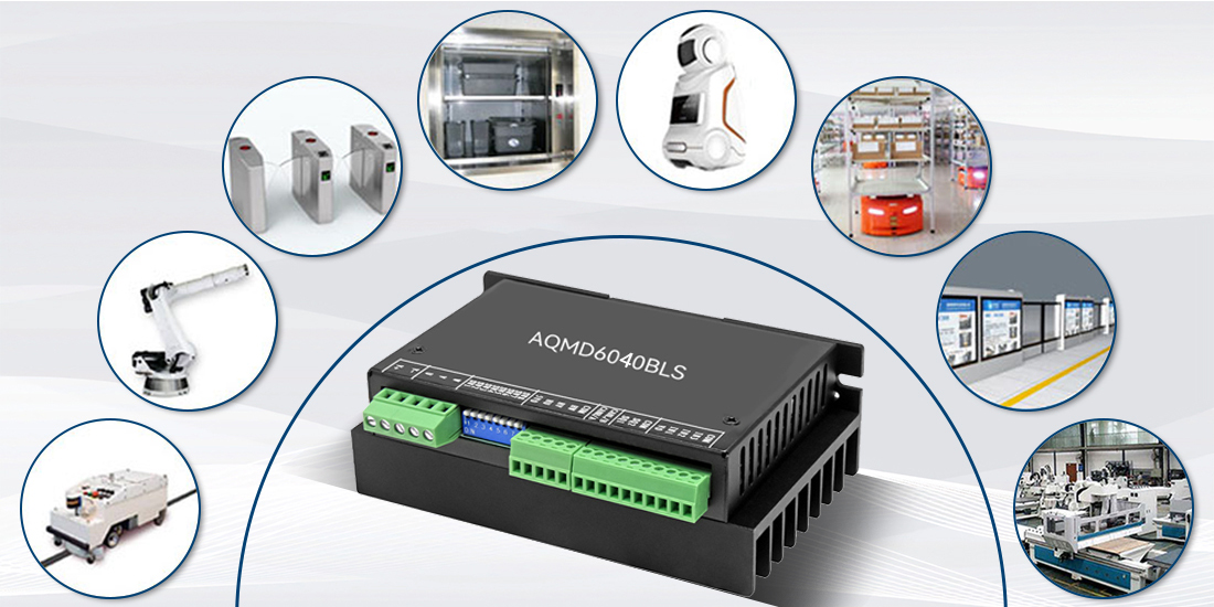
Application
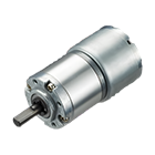
Application scope: AGV intelligent carts, mechanical arms, passage gates, food delivery elevators, service robots, warehouse robots, platform doors, various automatic control systems, etc
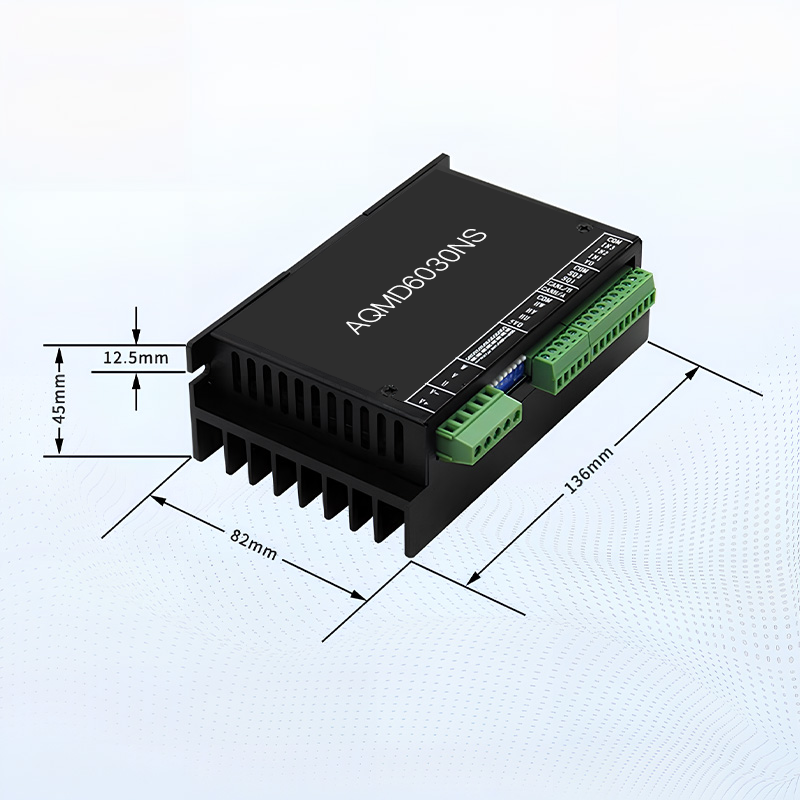
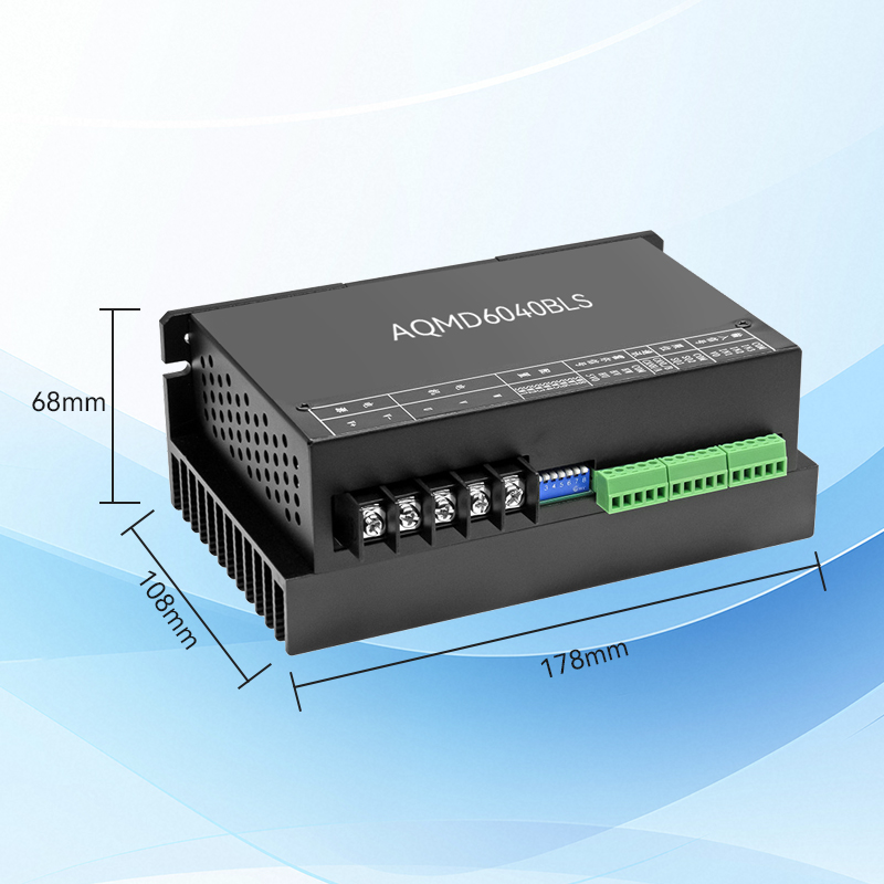
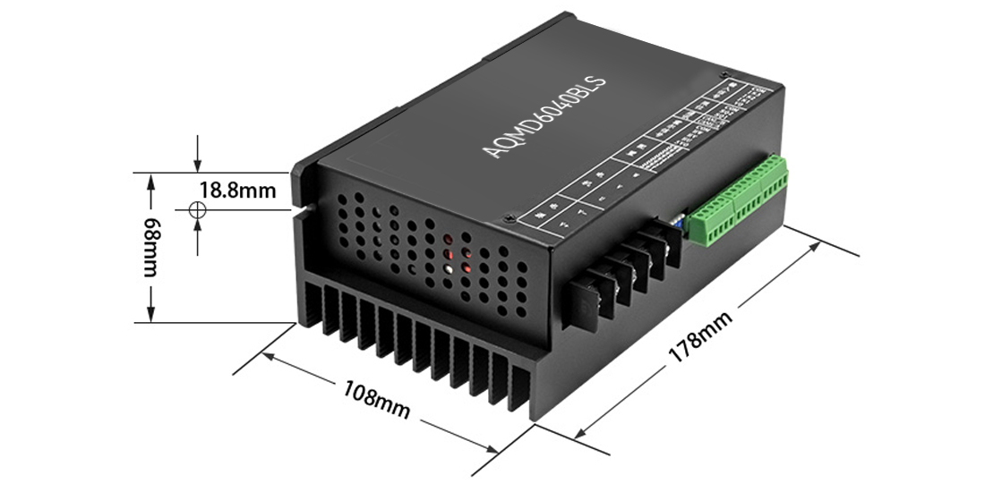
Dimensional drawing
Product parameters
Note: This driver is suitable for DC inductive brushless motors | ||||
Parameter comparison of AQMD_BLS-ExF series drivers | ||||
Project | AQMD6010BLS | AQMD6020BLS | AQMD6030BLS | AQMD6040BLS |
-E2F | -E2F/E3F | -E2F/E3F | -E2F | |
(Model 9-60V 10A) | (Model 9-60V 20A) | (Model 9-60V 25A) | (Model 9-60V 35A) | |
Control signal type | Potentiometer, analog quantity, PWM, frequency, pulse, level, switch quantity, 485/CAN communication control | |||
Motor control mode | Duty cycle (open-loop) speed regulation, speed closed-loop, position closed-loop, and torque limit control | |||
Position control braking mode | Constant acceleration braking ensures more accurate and stable positioning | |||
Power supply voltage range | 9~60V | |||
Rated current (Can block the rotor current for a long time) | 10A | 16A | 25A | 35A |
Maximum output current | 20A(double current)/ | 35A(double current)/ | 40A(double current)/ | 50A(double current)/ |
12A(long time) | 20A(non-double current) | 30 years (long term) | 40A(long time) | |
Support motor speed | Square wave: 0~100000RPM | 0~20000RPM | ||
Sine wave: Recommended 0~20000RPM | ||||
Double current output | Support | Support | Support | Support |
Overload current limiting | Support | Support | Support | Support |
Blocked rotor shutdown | Support | Support | Support | Support |
Abnormal large current shutdown | Support | Support | Support | Support |
Internal temperature measurement | Support | Support | Support | Support |
Overheat current limiting/shutdown | ||||
Power supply voltage measurement | Support | Support | Support | Support |
Overvoltage/undervoltage shutdown | ||||
External dimensions | 136×82×45mm | 136×82×45mm | 136×82×45mm | 178×109×68mm |
Working environment temperature | -30C°~70C° | |||
Communication interface protection | ESD, E2F series 485/CAN isolation, E3F series 485/CAN common mode voltage protection | |||
Product Features
◆ Voltage range: 9-60V, rated current: 10A/16A/25A/35A, maximum current: 20A/35A/40A/50A;
◆ Potentiometer, 0-3.3/5/10V analog signal, 0/3.3/5/12/24V logic level, switch quantity, PWM, frequency, pulse, RS485/ CAN multiple input signals;
◆ Multiple speed regulation modes such as duty cycle speed regulation, torque control (constant current), speed closed-loop control (constant speed), and position closed-loop control (Angle/distance control);
◆ Support the free switching between square wave and sine wave driving modes, taking into account the real-time response of the square wave driving mode and the low-noise characteristics of the sine wave driving mode;
◆ Support the control of acceleration and deceleration buffer time and acceleration during acceleration and deceleration. It can automatically accelerate and decelerate within the specified stroke and precisely position.
◆ PID regulation of motor current. The maximum starting/load current and braking (braking) current can be configured separately. Motor overload/locked-rotor current-limiting stop, as well as instantaneous high current monitoring to prevent overcurrent damage to the motor or driver.
◆Support internal temperature monitoring of the driver and configurable overheat protection temperature;
◆ Support internal monitoring of the driver power supply voltage, and the overvoltage/undervoltage shutdown monitoring values can be configured;
◆ Supports double current output, and can output a large torque during startup and heavy load.
◆Support motor speed measurement and motor locked-rotor detection; Supports external limit switch limit and locked-rotor limit.
◆ 485/CAN communication isolation or common mode voltage protection; Supports 485/CAN multi-site communication, facilitating control by various controllers (such as single-chip microcomputers, PCS or PLCS), and supports communication interruption and stoppage protection.
◆ Extremely small PWM dead time, only 0.5 μ s, with an effective PWM range of 0.1% to 100%; With a PWM frequency of 18kHz/20kHz, there is no PWM noise during motor speed regulation.
◆ Signal interface overvoltage protection. The signal interface can withstand a maximum voltage of 25V.
◆ Interface ESD protection, capable of adapting to complex on-site environments;
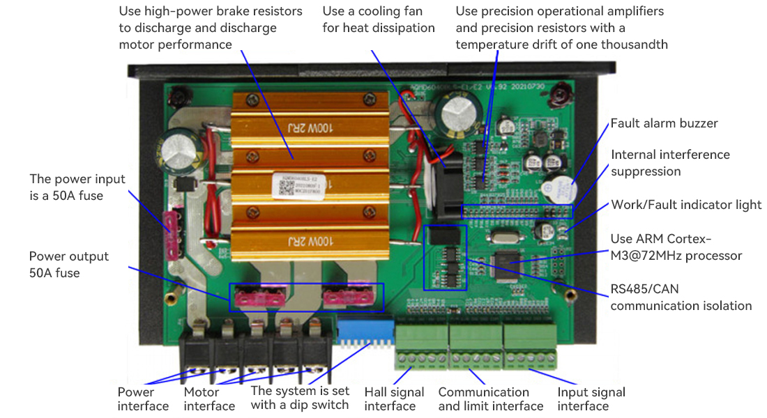
◆ Use the ARM Cortex-M3/M4 processor.
Performance comparison of drive modes | ||
Project | Square wave driving mode | F0C mode |
Motor torque pulsation | big | Small (with obvious advantages at low speeds) |
Noise when the motor is reversing | Large (especially under heavy load) | It has obvious advantages at low speeds |
Support motor speed | Suitable for both high and low speeds | Not suitable for ultra-high speed |
Note: | ||
Technical parameters
Project | Parameters | |||
AQMD6010BLS | AQMD6020BLS | AQMD6030BLS | AQMD6040BLS | |
Power input voltage | DC 9V~60V | |||
Rated output current | 10A | 16A | 25A | 35A |
Maximum long-term output current | 12A | 18A | 30A | 40A |
Maximum double current output current | 20A | 35A | 40A | 50A |
Maximum soft braking current | 6A | 6A | 12A | 20A |
Maximum matching motor | 12V~70W | 12V~100W | 12V~180W | 12V~240W |
Support the motor speed range | Square wave: 0-100,000 RPM | 0~20000RPM | ||
Potentiometer resistance value | 10K~50K | |||
Input signal interface withstand voltage | -0.5V~+25V | |||
Single-ended analog signal voltage range | Any within the range of 0 to 10V | |||
Differential analog signal voltage range | Any within the range of -3.3V to +3.3V | |||
Logic level voltage range | Any within the range of 0 to 24V, such as LvTTL,TTL,HvTTL, etc | |||
RS485 communication parameter range | The baud rate ranges from 9600 to 115200bps, with 8 data bits. It supports odd, even, and unchecked, as well as check bits and stop bits | |||
Support for Modbus | Supports Modbus-RTU, supports 03H, 06H, and 10H function codes, and can configure the slave station address range from 1 to 127. | |||
CAN communication parameter range | The baud rate is 10k to 1Mbps | |||
Temperature measurement range | -40℃~125℃ | |||
Effective detection range of voltage | 8~66V | |||
Working temperature | Suggestion: -30℃ to 70℃, maximum: -40℃ to 85℃ | |||
External dimensions | 136×82×45mm | |||
Configuration of dip switches | ||||
1.Control mode configuration | ||||
SW1-SW7 | SW8 | Control mode | ||
Arbitrary | OFF | Digital/analog signal control mode | ||
Slave station address | ON | 485 communication control mode | ||
2.Signal source selection | ||||
SW4 | SW5 | SW8 | Signal source | |
OFF | OFF | OFF | Potentiometer | |
ON | OFF | OFF | Analog signal | |
OFF | ON | OFF | PWM/ Pulse/frequency | |
ON | ON | OFF | Built-in program | |
3.Working mode configuration | ||||
SW4-SW5 | SW6-SW7 | SW8 | Speed regulation mode | |
It is not ON at the same time | OFF OFF | OFF | Duty cycle speed regulation | |
ON OFF | OFF | Torque control | ||
OFF ON | OFF | Speed closed-loop control | ||
ON ON | OFF | Position closed-loop control | ||
At the same time, be ON | OFF OFF | OFF | Motor learning | |
ON OFF | OFF | Itinerary learning | ||
OFF ON | OFF | Preset speed control | ||
ON ON | OFF | Retain | ||
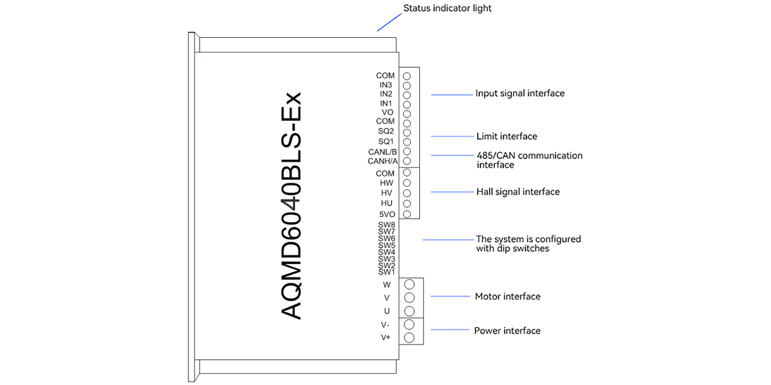
Wiring definition
Typical usage
1、The connection method of single potentiometer duty cycle/closed-loop speed regulation point control

The working process of the point control mode using potentiometer speed regulation is as follows: Press B1, the motor rotates forward, and the speed is adjusted using the potentiometer. B1 pops up and the motor stops. When the forward rotation limit is reached, the motor stops. Pressing B1 again is ineffective. Press B2, the motor rotates in reverse, and the speed is adjusted using a potentiometer. B2 pops up and the motor stops. When the reverse limit is reached, the motor stops. Pressing B2 again is invalid.
2.Connection method of PLC analog signal duty cycle/closed-loop speed regulation
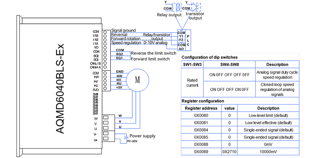
The working process of this connection method is as follows: IN1 is connected to the AO port of the PLC for speed regulation. IN2 and Y2 of the PLC control the direction of the motor. IN3 is connected to Y1 of the PLC to control the emergency stop of the motor.
3. The connection method of the PWM signal duty cycle/closed-loop speed regulation of the single-chip microcomputer
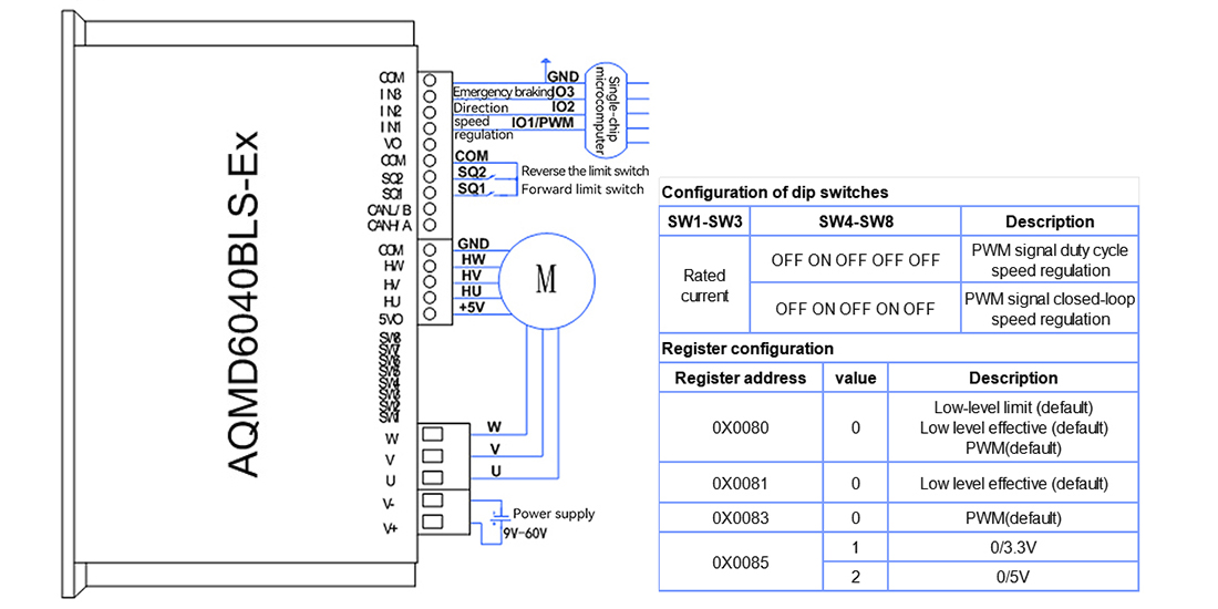
The working process of this connection method is as follows: Ground the power supply of the single-chip microcomputer to the COM port of the driver module. Pin IN1 is connected to the PWM output of the single-chip microcomputer for speed regulation. IN2 and IN3 are connected to the two IO ports of the single-chip microcomputer to control the forward and reverse rotation of the motor as well as emergency braking.
4. Connection method for position control of pulse signals from single-chip microcomputers
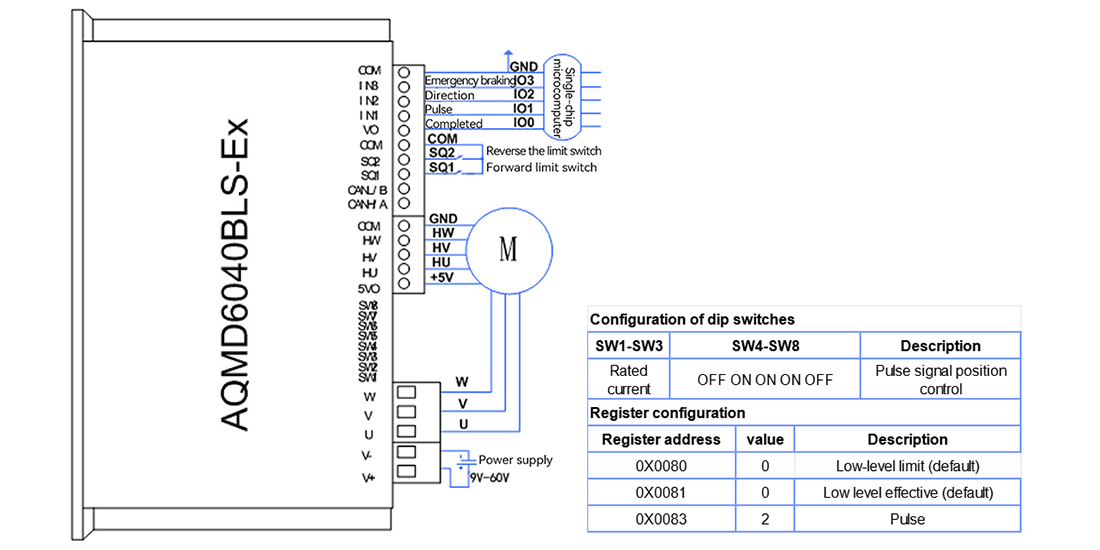
The working process of this connection method is as follows: Ground the power supply of the single-chip microcomputer to the COM port of the driver module. IN1 is connected to IO1 of the single-chip microcomputer to determine the number of pulses, which is used for motor position control. The VO is connected to the IO0 of the single-chip microcomputer to complete signal control. IN2 and IN3 are connected to the two IO ports of the single-chip microcomputer to control the forward and reverse rotation of the motor as well as emergency braking.
5. Connection method of 485 multi-site control
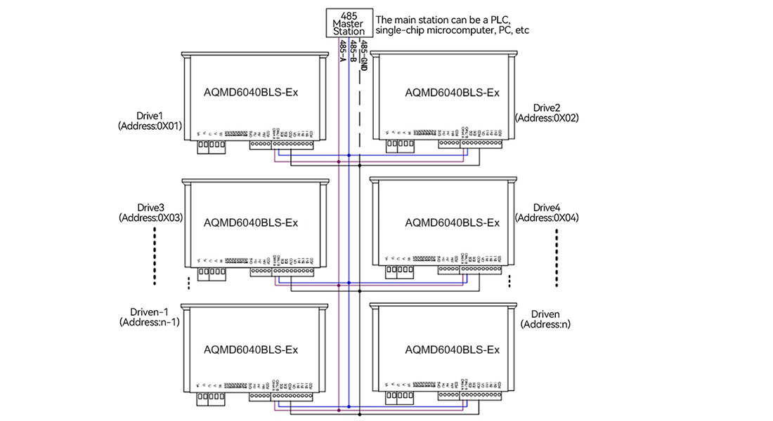
The 485 communication lines of each drive are connected in parallel in an A-A and B-B manner and then linked to A 485 master station. The 485 master station operates each drive independently based on the slave station address configured for the drive. The address configured for each drive should be unique and cannot be duplicated with other drives.
6. Connection method of CAN multi-node control
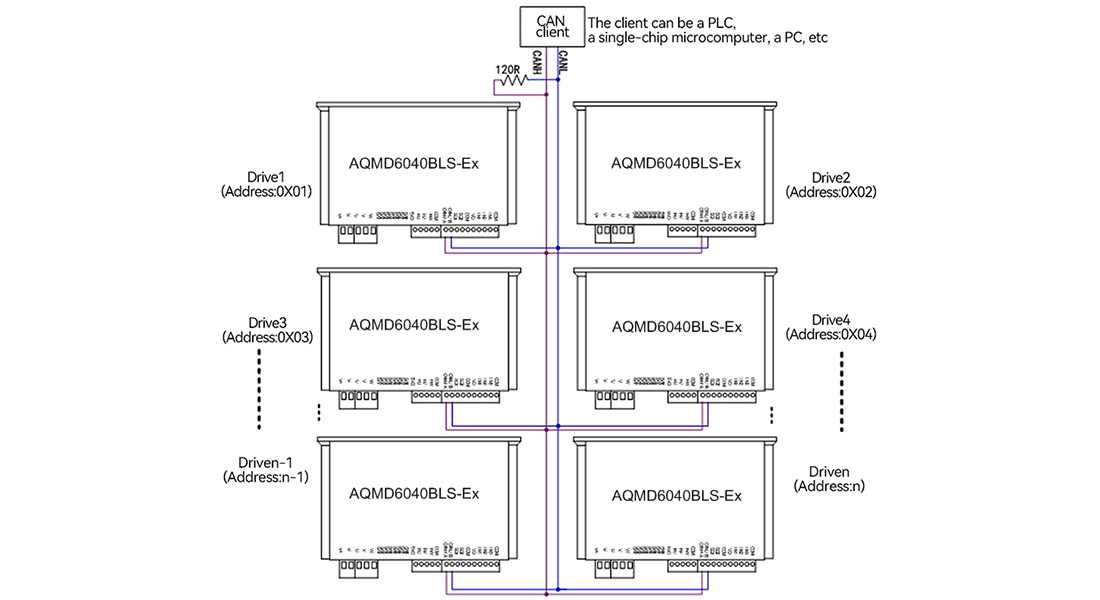
The CAN communication lines of each driver are connected in parallel in the CANH-CANH and CANL-CANL manner to the CAN client. At least one 120Ω resistor is connected in parallel on the CAN bus. The CAN client operates each driver independently based on the node ID configured by the driver. The node ID configured for each drive should be unique and cannot be duplicated with other drives.
Sample program
We provide PC sample programs that can be used to configure parameters, debug motors or for secondary development.
Appendix: Selection reference
Selection Table of AQMD_BLS Series DC Inductive Brushless Motor Driver
Model number | Functional characteristics | Maximum fit | Maximum current / | Energy braking | Control signal | Product size |
AQMD2403BLS-M | ● Minimal size | 12V18W | 6A/3A | 3A, do not brake frequently with high current | Single/dual potentiometer, 0-3.3V analog signal, logic level, switch, key, PWM, pulse, frequency, RS485 | 45x45x18mm bare board |
AQMD3605BLS-B2 | ● Overheat protection | 12V-30W | 10A/5A | 3A, do not brake frequently with high current | Single/dual potentiometer, 0-3.3V analog signal, logic level, switch, key, PWM, pulse/frequency, RS485 | 70x65x2lmm Raw board |
AQMD2408BLS-M | ● Compact size | 12V-45W | 16A/8A | 3A, non-battery power can not be high current frequent brake reversing | Single/dual potentiometer, 0-3.3V analog signal, logic level, switch, key, PWM, pulse/frequency, RS485 | 55x55x17mm bare board |
AQMD3608BLS | ● Rail mounting | 12V-50W | 10A/8A | 3A, do not brake frequently with high current | Single/dual potentiometer, 0-3.3/5/10V analog signal, logic level, switch, key, PWM, pulse/frequency, RS485 | 92x87x30mm bare plate |
AQMD6008BLS-T | ● Compact case | 12V-50W | 16A/8A | 3A | Single/dual potentiometer, 0-3.3V analog signal, logic level, switch, key, PWM, pulse/frequency, RS485 | 93x56x20.5mm |
AOMD6008BLS-TE/-I | Single/dual potentiometer, 0-3.3/5/10V analog signal, logic level, switch, key, PWM/ pulse/frequency, RS485/CAN | |||||
AOMMD6008BLS-TF/-I | ||||||
AQMD6010BLS-B2 | ● Overheat protection | 12V-60W | 20A/10A | 6A | Single/dual potentiometer, 0-3.3/5/10V analog signal, logic level, switch, key, PWM/ pulse/frequency, RS485 | 136x82x45mm |
AOMD6010BLS-E2 |
| 20A/10A | 6A | Single/dual potentiometer, 0-3.3/5/10V analog signal, logic level, switch, key, PWM/ pulse/frequency, RS485/CAN | 136x82x45mm | |
AOMD6010BLS-E2F | 8A | |||||
AQMD6020BLS-E2/E3 |
| 12V-100W | 35A/16A | 6A | Single/dual potentiometer, 0-3.3/5/10V analog signal, logic level, switch, key, PWM/ pulse/frequency, RS485/CAN | 136x82x45mm |
AOMD6020BLS-E2F | 8A | |||||
AQMD6030BLS-E2/E3 |
| 12V-180W | 40A/25A | 12A | Single/dual potentiometer, 0-3.3/5/10V analog signal, logic level, switch, key, PWM/ pulse/frequency, RS485/CAN | 136x82x45mm |
AQMD6030BLS-E2F | ||||||
AOMD6040BLS-E2 |
| 12V-240W | 50A/35A | 20A | Single/dual potentiometer, 0-3.3/5/10V analog signal, 0-3.3/5/24V logic level, switch, key, PWM, pulse, frequency, RS485/CAN communication | 178x108x68mm |
AQMD6040BLS-E2F | ||||||
AQMD12H10BLS-E2 | ● Overheat protection | 24V-200W | 25A/12A | 6A | Single/dual potentiometer, 0-3.3/5/10V analog signal, logic level, switch, key, PWM/ pulse/frequency, RS485/CAN | 136x82x45mm |
AOMD12H30BLS-E2 | ● Overheat protection | 24V-500W | 45A/30A | 12A | Single/dual potentiometer, 0-3.3/5/10V analog signal, logic level, switch, key, PWM/ pulse/frequency, RS485/CAN | 178x108x68m1 |
AQMD22A04BLS-E2 | ● Overheat protection | 72V-175W | 7A/3.5A | 3A | Single/dual potentiometer, 0-3.3/5/10V analog signal, logic level, switch, key, PWM/ pulse/frequency, RS485/CAN | 136x82x45mm |
After-sale guarantee
After-sales service: We offer comprehensive after-sales technical support. If you encounter any problems during use, our professional after-sales engineer team will respond promptly and provide you with detailed solutions through phone calls, emails or remote assistance. We also offer regular follow-ups on our products to understand their usage and collect your feedback, so as to continuously optimize our products and services. In addition, in strict accordance with the warranty policy, we offer free repair or replacement services for products that have quality issues within the warranty period, ensuring you have no worries.