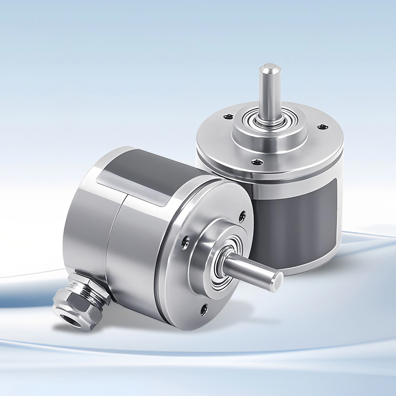
Product Description
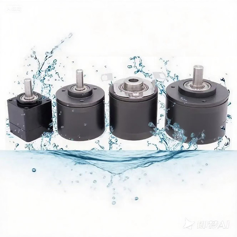
◆ IP68 waterproof (1m deep), dust-proof, salt fog-proof, vibration-resistant;
◆ Single circle 0~360° absolute type, power-off memory;
◆ Can be made into electronic multi-circle, up to several million circles;
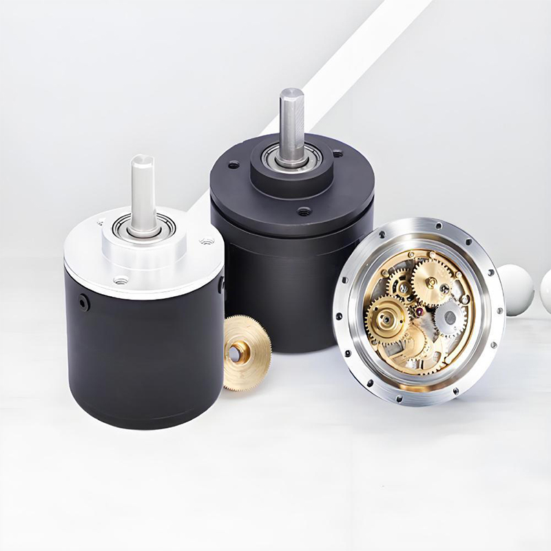
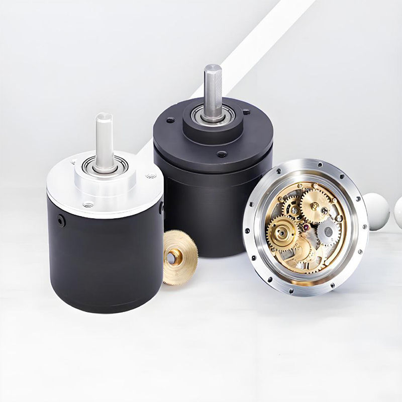
◆ Precise mechanical gear multi-circle, without internal battery;
◆ Resolution up to 17 bits, accuracy up to 0.05 degrees;
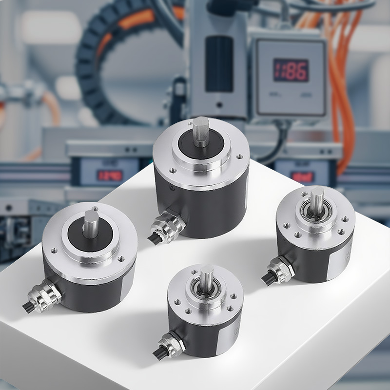
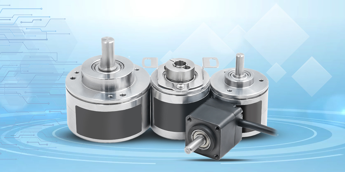
◆ Minimum volume 27*27mm, stainless iron casing, stainless steel bearings, industrial-grade encoder;
◆ Wide voltage range, passed EMC test, strong anti-interference ability, stable performance;
◆ Parameters can be set through communication protocol or upper computer software, operation is intuitive and simple;
◆ Supports query mode and automatic return mode, feedback position and speed; programmable parameters such as baud rate, reset function, counting direction and speed feedback;
Product parameters
Electrical parameters | |||
Communication interface | RS485、ModBus RTU、RS232、CAN、CANopen、SSI、BISS、SPI、High-speed RS485 protocol (compatible with Momochi River) | ||
Number of rounds | Single lap, multiple laps: 16, 32, 64, 1200, 4320, 10800, 21600, 34891, 69872 laps (customizable) | ||
Single lap resolution | 10bit、12bit、14bit 15bit、16bit、17bit | ||
Baud rate | RS485/RS232/ModBus RTU:9600~115200(Default9600);CAN:100K~1M(Default500K) SSI:100K-5M | ||
Working voltage | 5~24V | Linearity | 0.10% |
Kernel refresh cycle | 50uS | Electrical lifespan | >100000h |
Working current | Single coil 50mA; Multiple coils 100mA | Station number, address | 1-255(Default 1) |
Mechanical parameters | |||
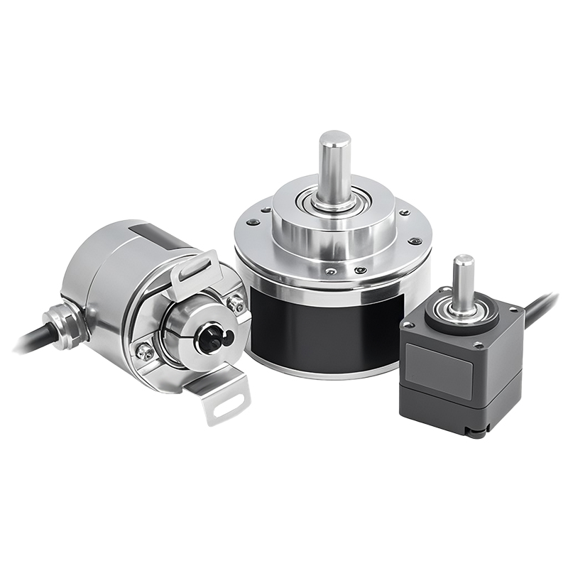
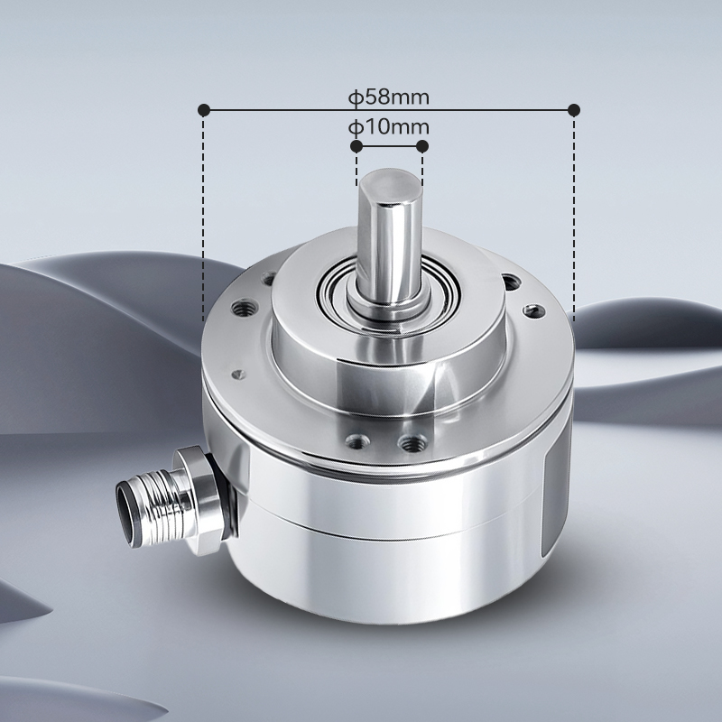
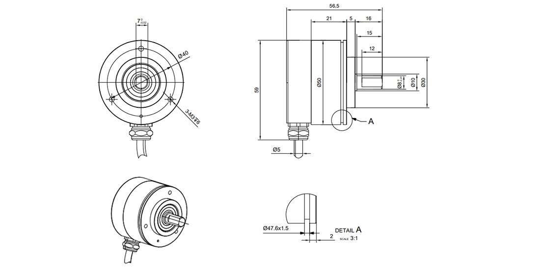
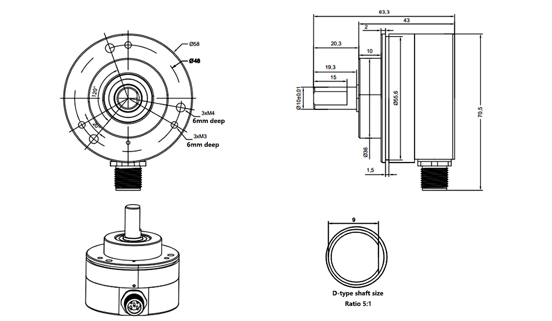
Dimensions of the shape | 27mm * 27mm - 6mm shaft, φ39mm - 6mm shaft, φ39mm - 8mm blind hole, φ39mm - 8mm clamp, φ50mm - 8mm shaft, φ58 - 10mm shaft | ||
Shell/Fillet material | Stainless iron | Maximum mechanical speed | 8000 revolutions per minute for a single lap, 3000 revolutions per minute for multiple laps. |
Shaft material | Stainless steel shaft (customizable shaft size) | Maximum starting torque | 0.006Nm |
Bearing material | Stainless steel | Weight | 86 - 200 g (including 1.2-meter shielding wire, customizable wire length) |
The maximum load of the shaft | Axial force: 20 N, Radial force: 80 N | Salt spray protection | Yes |
Environmental parameters | |||
Working temperature | -40~+85℃ | Humidity | 98% (no condensation) |
Storage temperature | -40~+85℃ | Protection level | IP68 |
Definition of Wiring | |||||
Interface type | RS485 | RS232 | CANbus | CANopen | SPI |
Red line | Positive terminal of the power supply | Positive terminal of the power supply | Positive terminal of the power supply | Positive terminal of the power supply | Positive terminal of the power supply |
Black line | OV position | OV position | OV position | OV position | OV position |
Yellow line | Zero (ZR) | Zero (ZR) | Zero (ZR) | Zero (ZR) | CS |
Green line | RS485B | TX | CANH | CANH | CLK |
White line | RS485A | RX | CANL | CANL | DO |
SSI/BISS | ||||||||
Color | Red | Black | Green | Brown | White | Grey | yellow | Orange |
Definition | 5-24V | GND(OV) | CLOCK+ | CLOCK- | DATA+ | DATA- | Set to zero | Direction |
Model Description | |||||||||||||
Outer diameter of the main body | Diameter of the shaft/hole: | Number of laps: | ||||||||||||
┃ | ┃ | ||||||||||||
R | 38 | 06D | - | 17 | S1 | S | - | IP68 | |||||
┃ | ┃ | ┃ | ┃ | ||||||||||
Communication Protocol: | 分辨率: | Outlining method | Protection level | ||||||||||
For example: R3806D-17S1S-IP68 Represents a single-ring absolute encoder with RS485 output, outer diameter of the main body 38mm, solid shaft
6mm, resolution 17 bits, side outlet, IP68 waterproof.
How to Choose Single-Loop/Multi-Loop Absolute Value Encoders
The single-circle absolute encoder can only remember the data within one circle (0 - 360°) after power loss. Once the rotation exceeds one full circle, the value starts counting from 0 again. In the absence of power, the single circle can be used as an electronic multi-circle counter.
Multi-turn absolute encoder is like the "minute hand + hour hand" of a clock. It can not only indicate the position of the "minute hand" within the 0-360° cycle, but also provide the number of turns made by the "minute hand" through the "hour hand". After power loss, it can remember the data and the number of turns in a single turn, so it is defined as multi-turn. When the rotation exceeds the specified number of turns, the value starts counting from 0 again. Therefore, when choosing a multi-turn absolute encoder, it is necessary to select the number of turns slightly greater than the actual number of turns to be measured. In this way, even if the power is lost at any position within the entire measurement range (or after power loss, the device is rotated), it can still be remembered.
Dimension drawing
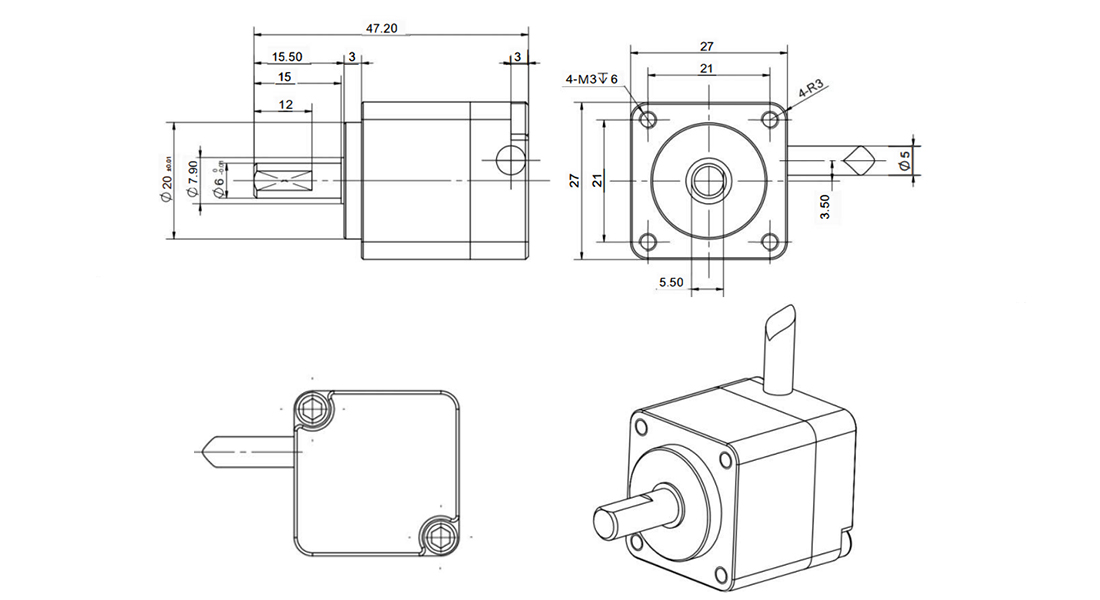
█ IP68 2706D Encoder
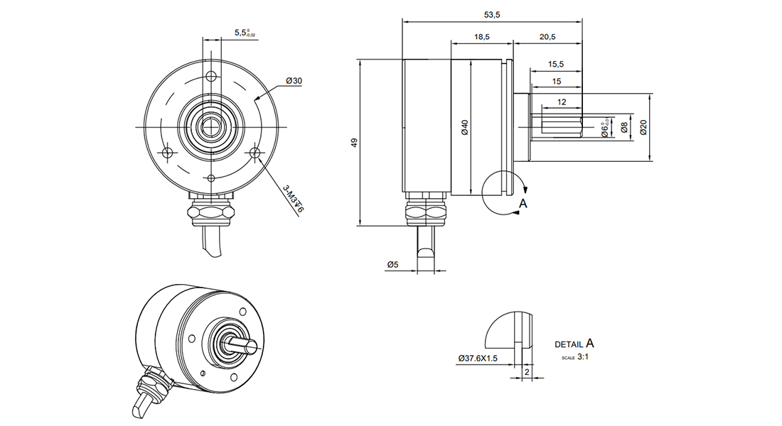
█ IP68 3806D Encoder
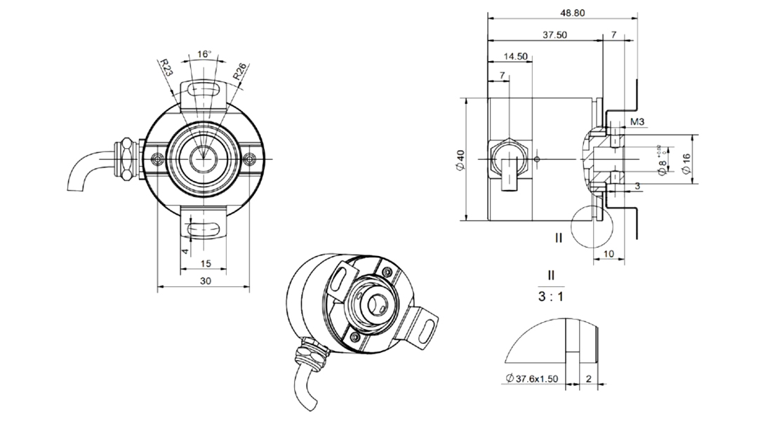
█ IP68 3808B Encoder
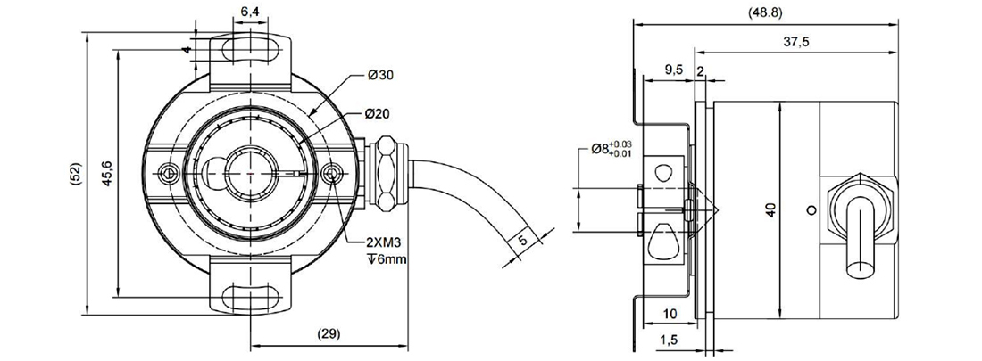
█ IP68 3808G Encoder
█ IP68 5008D Encoder
█ IP68 5810D Encoder
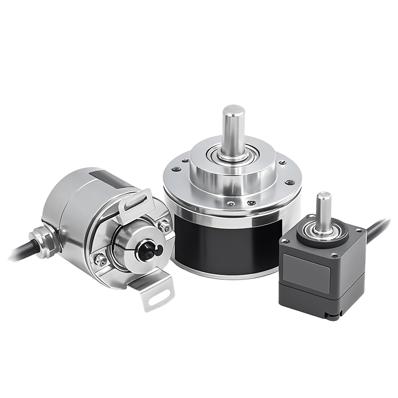
Product Display
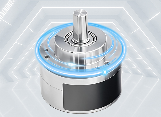
The single-turn encoder can be used as an electronic multi-turn encoder without power loss, with a maximum of up to millions of turns. It also has a measurement speed function, making it convenient for calculation. Any position within the measurement range is unique.
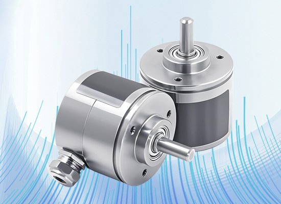
The absolute value encoder products offer a wide range of stable types, and the communication protocols include RS485 Modbus, CANopen, and SSL, which can meet the measurement and control requirements for speed, angle and position of customers from different industries.
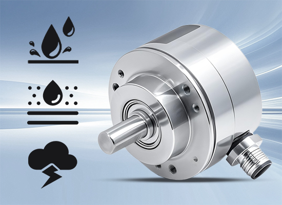
Imported chips, high stability, high-resolution stainless steel shaft/frame, imported NMB bearings, high-quality iron casing, with excellent resistance to mechanical damage, ultra-flexible drag chain cable with shielding layer, resistant to folding and stretching, more stable transmission. 360° non-contact sensor, compared to photoelectric encoders, it is more resistant to vibration, impact, water, oil, dirt, temperature and humidity changes.
Communication Protocol
Single-loop RS485 communication protocol (standard ODBUS-RTU)
Communication is carried out using the MODBUS-RTU (national standard GB/T19582-2008) communication protocol. It supports one master station controlling multiple slave stations. Through the built-in upper computer, 127 slave station addresses can be configured. The master station can be a single chip microcontroller, PLC or PC, etc.
Supports MODBUS's 0x03 (read holding register), 0x06 (write single register), 0x10 (write multiple registers).
Register definition | ||||
Register address | Description | Range of values | Support function code | Note |
0x0000~0x0001 | Encoder value | 0~0xFFFFFFFF(0~4294967295) | 0x03 | — |
0x0004 | Encoder address | 1~127 | 0x06 | Postal Address |
0x0005 | Baud rate | 0x0000~0x0004 | 0x06 | Default:9600; |
0x0006 | Encoder mode | 0x0000~0x0001 | 0x06 | 0x00: Query Mode |
Encoder communication instance | ||||
Single-loop CAN communication protocol
Adopt the CAN2.0B standard frame communication protocol, | ||||||||
Identifier ID | Data[0] | Data[1] | Data[2] | Data[3] | Data[4] | Data[5] | Data[6] | Data[7] |
0X01 | 0X04 | 0X01 | 0X01 | 0X00 | —— | —— | —— | —— |
Returned data: Data field length 7; | ||||||||
Identifier ID | Data[0] | Data[1] | Data[2] | Data[3] | Data[4] | Data[5] | Data[6] | Data[7] |
0X01 | 0X07 | 0X01 | 0X01 | 0X45 | 0X23 | 0X01 | 0X00 | —— |
Instruction List V2.01 | ||||||||
CAN command | Function Description | (Encoder address ID is defaulted to 01) | ||||||
0x01 | Read the encoder value. | Issue: [0x04][0x01][0x01][0x00] Return | ||||||
0x02 | Set the encoder ID, value range: 0 - 255 | Issue: [0x04][0x01][0x02][0x08] | ||||||
0x03 | Set CAN communication baud rate | Issue: [0x04][0x01][0x03][0x01] | ||||||
0x04 | Set encoder mode | Issue/Disseminate [0x04][0x01][0x04][0xAA] | ||||||
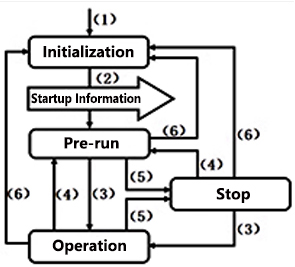
CANOPEN communication protocol
Before using the CANopen encoder, please install the EDS file on the CANopen main controller. For specific details, please contact customer service.
State machine | Serial Number Description |
| (1) Power on |
(2) Initialization completed, automatic sending of startup information | |
(3) NMT message "Start remote node" | |
(4) NMT message "performing pre-run" | |
(5) NMT message "Shutdown remote node" | |
(6) NMT message "Reset Node" or "Reset Communication" |
Boot-up object | |
COB-ID (Hexadecimal) | 1 byte of CAN data |
700+ nodes' IDs | 00 |
PDO object | ||||
Logo | 4-byte CAN data | |||
COD-ID (Hexadecimal) | Byte 0 | Byte 1 | Byte 2 | Byte 3 |
Function code Node ID | 27-20 | 215-28 | 223-216 | 231-224 |
—— | Low byte | … | … | High byte |
When setting the parameters, an example of data exchange between the main controller and the encoder. "ID" is used to represent the address of the encoder. The numerical values are expressed in hexadecimal notation. | ||||
Set running and pre-running states | |||
NMT message | COB-ID | Command | Command |
Operation | 000 | 01 | ID |
Pre-run | 000 | 80 | ID |
Application Cases
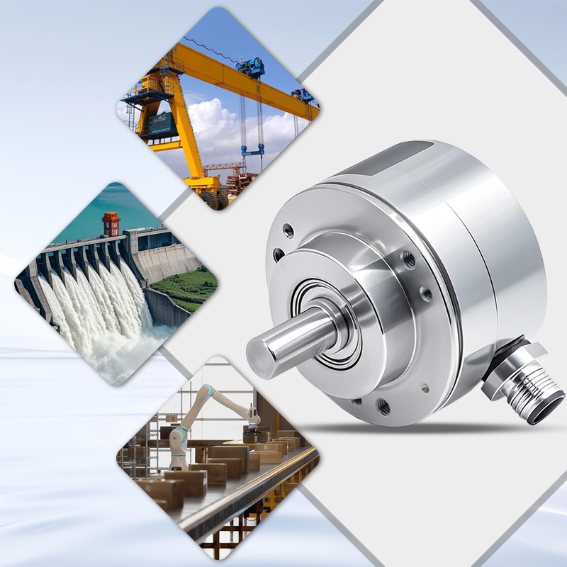
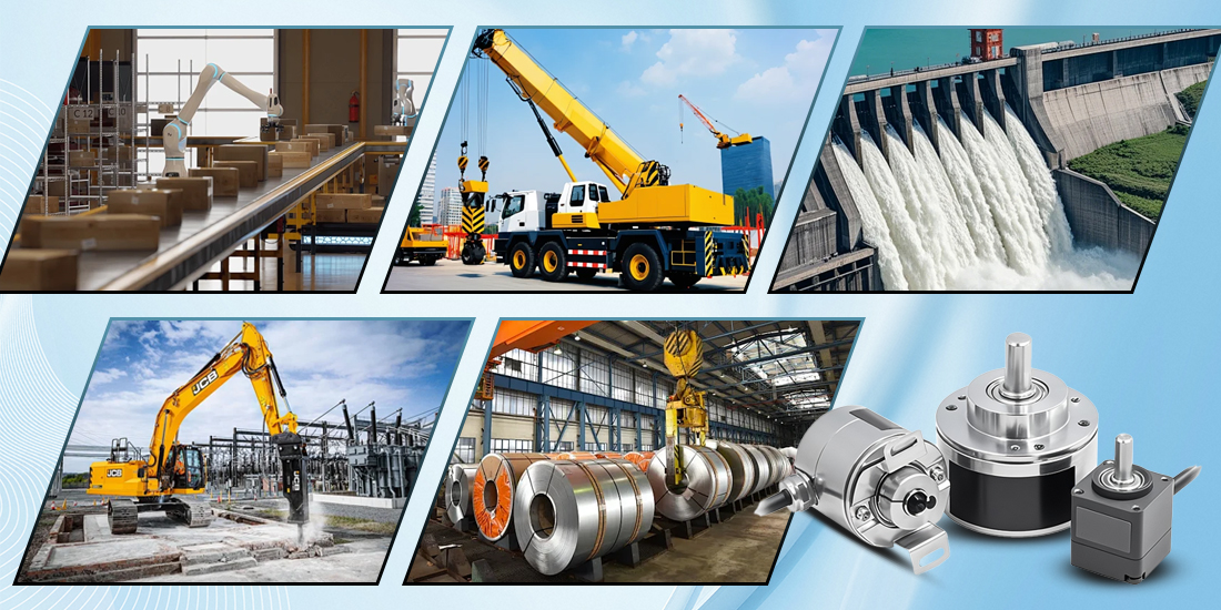
It is widely used in the steel industry, automated assembly lines, transportation equipment, textile machinery, port machinery, plastic machinery, lifting machinery, pressure machinery, glass machinery, printing machinery, wood machinery, packaging machinery, machine tools, logistics machinery, tire machinery, elevator automation, cement plant industrial robots, inkjet printers, construction machinery, etc. for reliable/precise measurement of height, travel, angle and speed.
Installation Precautions
● The encoder is a precision instrument. During installation, it is strictly prohibited to strike, drop, or collide it.
● The encoder should be connected to the machinery using flexible connectors or elastic supports. Avoid hard damage caused by rigid connection and misalignment.
● Pay attention to whether the environment and humidity are within the requirements for the encoder's use. Pay attention to the waterproof rating of the encoder. If necessary, please use waterproof covers and other measures.
● Although the encoder itself will not lose position information in an interference environment, it will cause interference to the data during the transmission process. Therefore, when there are motors or strong electromagnetic interference in the system, it is necessary to adopt isolation power supplies for power supply to the encoder and use double-shielded cables for external extended communication lines, etc.
● The outer shell of the encoder and the outer layer of the shielding wire should be well grounded to prevent damage to the encoder circuit caused by lightning strikes or high-voltage static electricity.
● In addition to allowing the zero-reset (yellow wire) to be grounded, all other signal lines of the encoder must not be short-circuited to each other. Avoid touching the signal lines when powered on to prevent damage to the output circuit.
Common Questions and Answers
01. Differences and Selection between Single-Wire Encoder and Multi-Wire Encoder
Absolute value encoders can be classified into "single-wire absolute value" and "multi-wire absolute value" encoders based on the range of the power-off memory.
"Single-wire absolute value" can only store position information within the range of 0 to 360°, while "multi-wire encoder" has a unique number of turns and angles within the range of the number of turns. Even if there is a power outage, it can still rotate and immediately feedback the current latest position information after re-powering.
Therefore, for measuring rotation within 360°, a single-wire encoder should be chosen. If the rotation exceeds 360°, a multi-wire absolute value encoder should be selected.
02. How high is the linear accuracy of multi-turn encoders? How long is their lifespan?
The highest linear accuracy of absolute value encoders is 0.1%, and there is no cumulative error;
Multi-turn absolute value encoders have a metal gear structure inside. The gears are not subjected to force, and with the use of high-grade lubricating grease, the theoretical lifespan is extremely long; and the metal gears do not have temperature drift differences, and the output signal is precise and stable.
03. Can it be used in conjunction with PLC?
The multi-turn absolute encoder adopts standard Modbus RTU protocol, CAN bus, CANopen, etc. There is no need to consider replacing similar models. As long as the PLC supports the same protocol, it can be used. Technical support and PLC routine references can also be provided. Additionally, a multi-functional upper computer software can be provided for direct connection to the computer to set the encoder parameters.


