
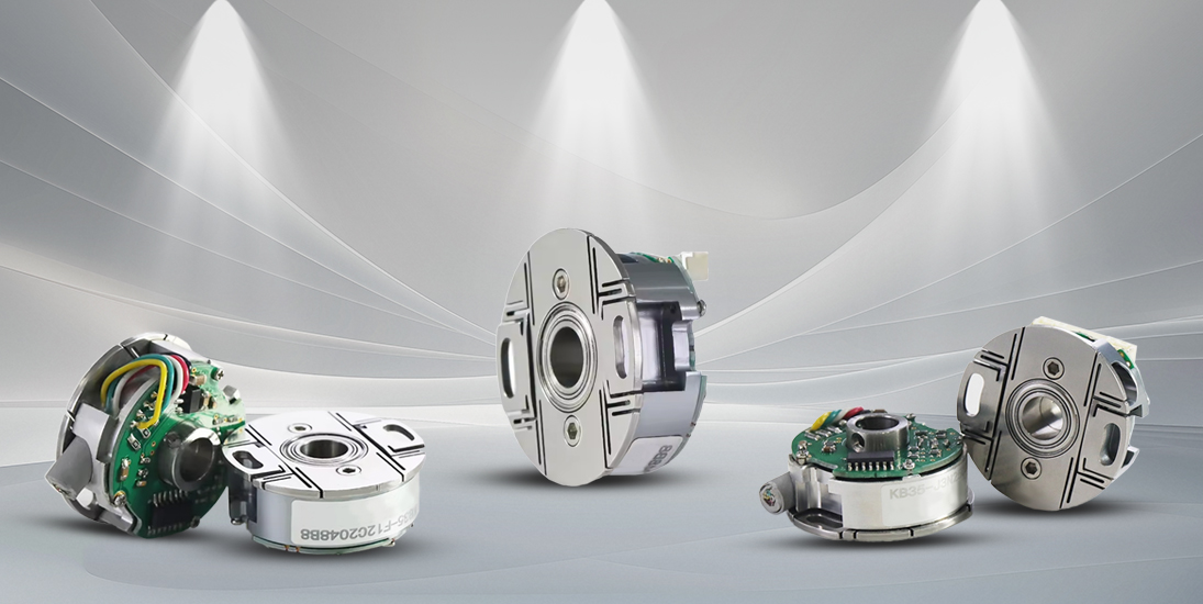
Product Description
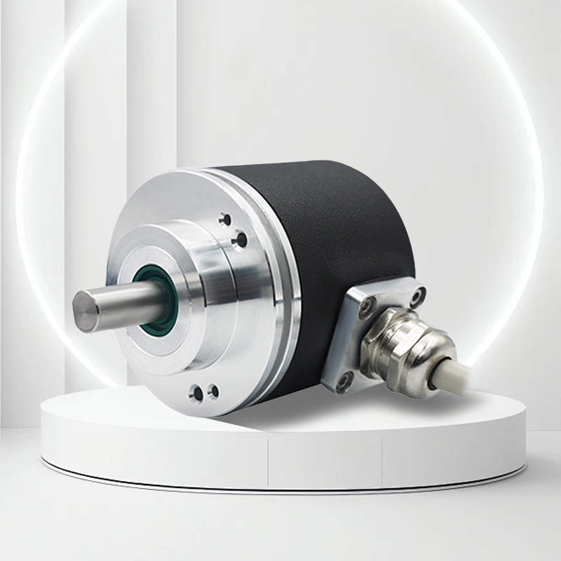
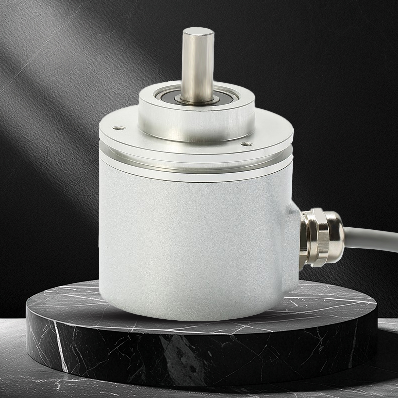
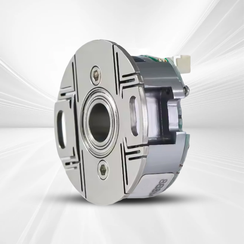
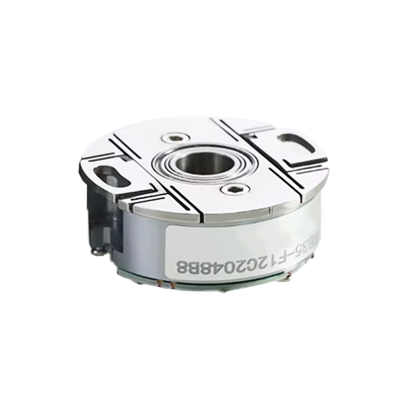
The KB35 incremental photoelectric encoder (through shaft) features a miniaturized design without protection grade, multiple electrical interfaces and resolutions, a compact structure and simple installation
Product Features |
|

Product parameters
Project | Basic parameters | |
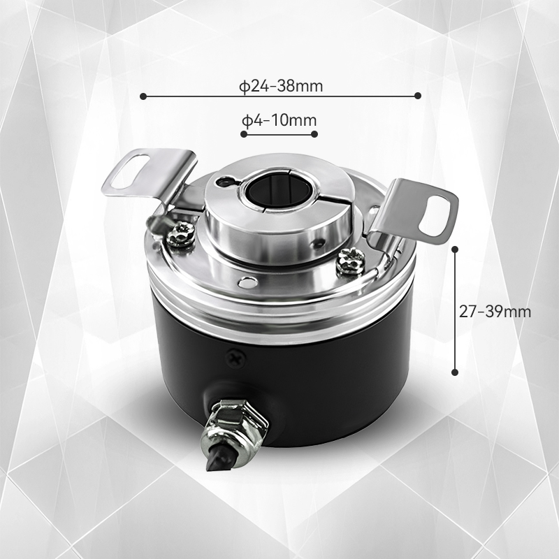
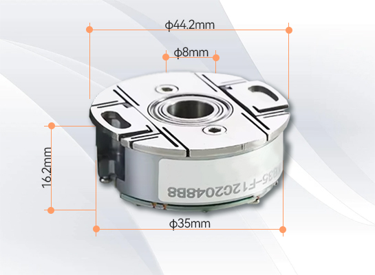
External dimensions | Outer diameter: 35mm | |
Thickness: 17mm | ||
Shaft diameter: 6mm/8mm | ||
Pulse | 1024; 2048; 2500; 3600; 5000; 7200; 10000; 14400; | |
1024/4; 1024/6; 1024/8; 250/4 250/6 2500/4; 2500/6; 2500/8; 5000/4; 5000/6; 5000/8; | ||
Output phase | Phase A,B,Z A-B-Z -,U,V,W | |
Power supply voltage | DC5V & DC8-30V | |
Qualification method | Radial cable & Radial socket | |
Output type | NPN collector open-circuit output | |
Push-pull output | ||
Differential output | TTL | |
HTL | ||
Ambient temperature | Operating temperature: -20 to +100° C | |
Storage temperature: -25 to +100° C (no condensation) | ||
Environmental humidity | Operation and storage: 35-85%RH (no condensation) | |
Line length | 500mm | |
Shell | Die-cast aluminum alloy | |
Packaging method | Paper box | |
Weight | 60g | |
Instructions for Use
1、Selection Guide | ||||||||||||||||
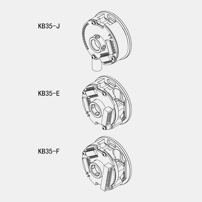
Model composition (Selection parameters) | ||||||||||||||||
KB35- | J | 12 | C | 2500/8 | Q8 | - | 000 | |||||||||
↑ | ↑ | ↑ | ↑ | ↑ | ↑ | ↑ | ↑ | ↑ | ||||||||
Series product models | Connection method: | Output phase number:
| Electrical interface | Resolution PPR: | Shaft diameter: (through) | Power supply voltage: | Special Specifications: | Management Number | ||||||||
Note: ① The Z belief sign is valid when it is at a low level; ② The Z belief sign is valid when it is at a high level. | ||||||||||||||||
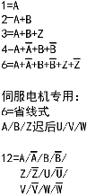
2、Output mode
2.1 Incremental Signal
2.2 Servo motor dedicated (with U.V.W)
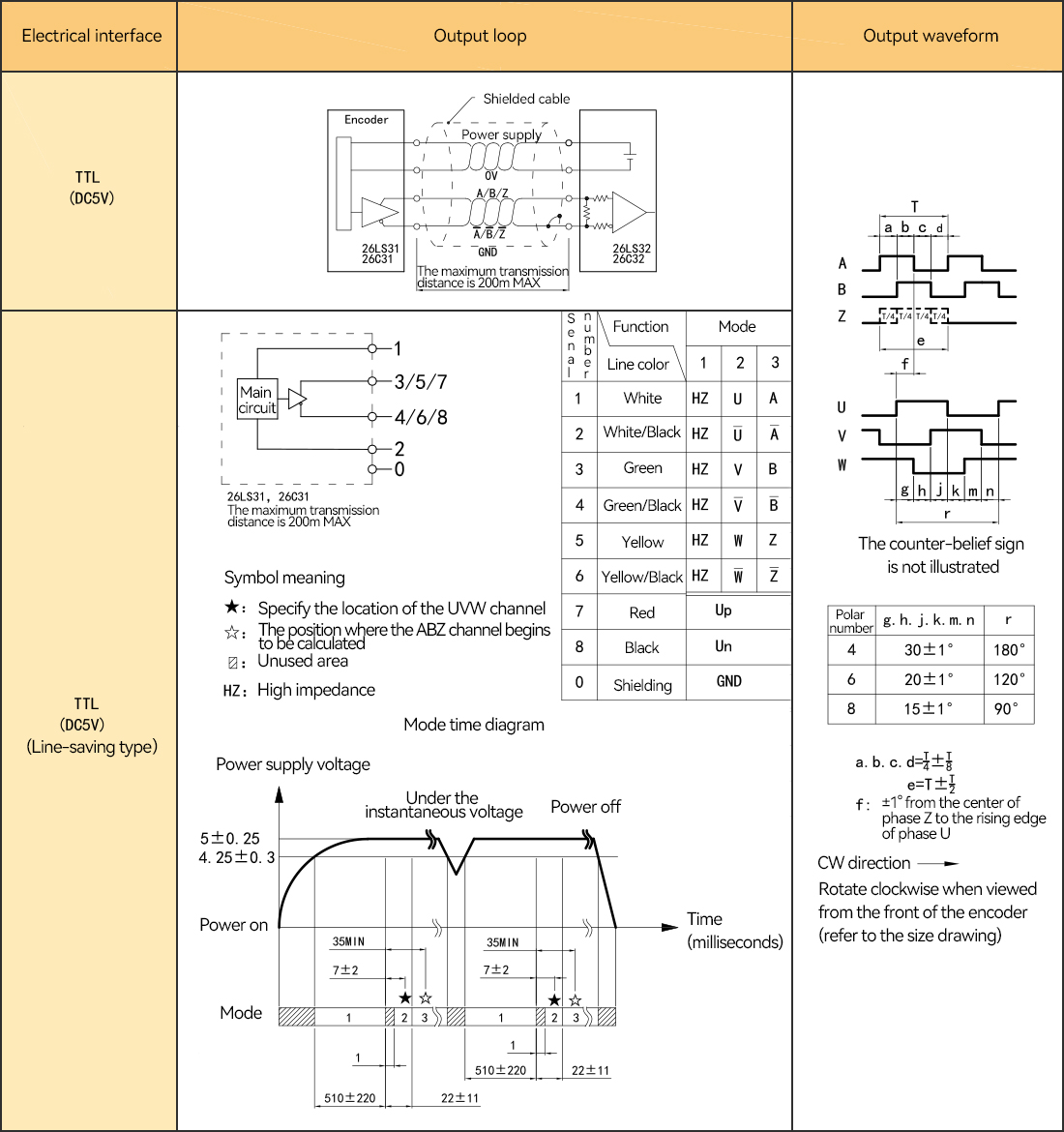
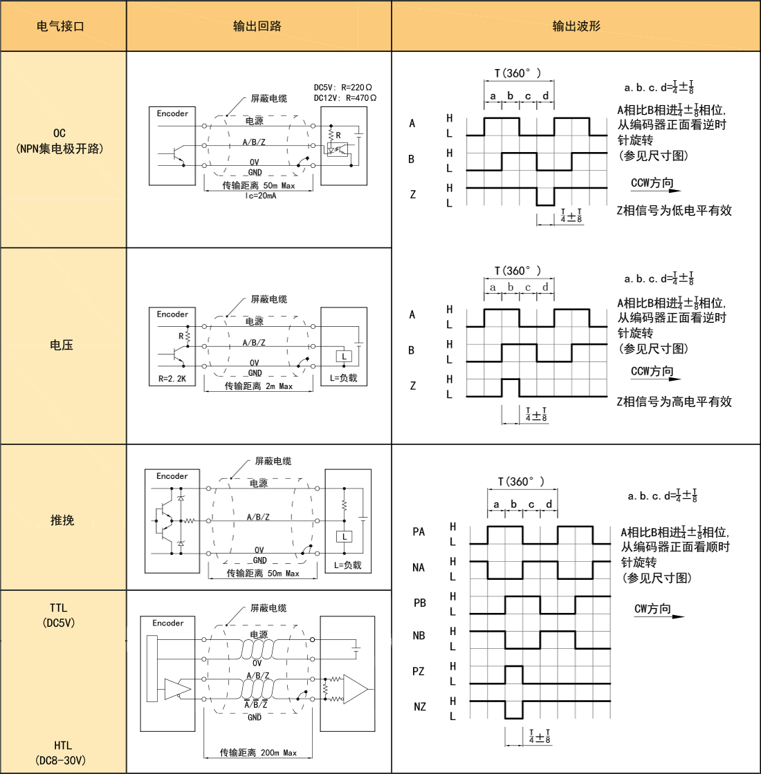
3. Electrical parameters
Project parameters | Output type | ||||||||
0C | Voltage | Push and pull | TTL | TTL | HTL | ||||
Power supply voltage | DC+5V±5%;DC8V-30V±5% | DC+5V±5% | DC8-30V±5% | ||||||
Consumed current | 100mA Max | 120mA Max | |||||||
Allow ripples | ≤3%rms | ||||||||
Maximum response frequency | 100KHz | 300KHz | 500KHz | ||||||
Output capacity | Output | Inflow | ≤30mA | 负载电阻2.2K | ≤30mA | ≤±20mA | ≤±50mA | ||
Electric current | Outflow | 一 | ≤10mA | ||||||
Output | “H” | 一 | 一 | ≥[(电源电压)-2.5V] | ≥2.5V | ≥Vcc-3 Voc | |||
Voltage | “L” | ≤0.4V | ≤0.7V(20mA以下) | ≤0.4V(30mA) | ≤0.5V | ≤1V VDc | |||
Load voltage | ≤DC30V | 一 | 一 | ||||||
Rising and falling time | Less than 2us (wire length: 2m) | Less than 1us (wire length: 2m) | |||||||
Insulation withstand voltage | AC500V 60s | ||||||||
Insulation impedance | 10MΩ | ||||||||
Duty cycle | 45% to 55% | ||||||||
Polarity reverse connection protection | √ | ||||||||
Short-circuit protection | √① | ||||||||
Phase difference between A and B | 90°±10°(At low frequency) | ||||||||
90°±20°(At high frequency) | |||||||||
Delayed action time ② | 一 | 510±220ms | 一 | ||||||
Shielded wire | The encoder body is not connected | ||||||||
① Short circuit with another cable or GND, with a maximum allowable time of 30 seconds.② When powered on, A.B.Z is the latest U.V.W time. | |||||||||
4. Mechanical specifications
Shaft diameter | φ6mm;φ8mm(Optional) |
Starting torque | Below 5.9×10⁻³N · m |
Inertial moment | Below 1.5×10⁻⁶kg · m² |
Allowable force of the shaft | Radial 30N Axial 20N |
Maximum allowable rotational speed | ≤6000 rpm |
Bearing life | Rated load: 1.5X10⁹, 100,000 hours at 2500RPM |
Outer shell | Aluminum alloy |
weight | About 60g |
5、Environmental parameters
Ambient temperature | During operation: -20 to +90℃(Repeatedly bent cable: -10℃) Storage temperature: -20 to +95℃ |
Environmental humidity | During operation and storage: 35-85%RH(no condensation) |
Vibration (durability) | Amplitude: 0.75mm,5-55HZ, 2 hours in each of the three axes |
Impact (durability) | 490m/s²11ms, three times in the X,Y, and Z directions |
Protection grade | no |
6、Wiring meter
6.1 0C&Voltage (Table 1)
Name | Incremental signal | Power supply voltage | ||||||
Socket pin number | 1 | 2 | 3 | 4 | 5 | 6 | 7 | 8 |
Line color | white | / | green | / | yellow | / | red | black |
Function | A | / | B | / | Z | / | Up | 0V |
Name | Incremental signal | Power supply voltage | ||||||
Socket pin number | 1 | 2 | 3 | 4 | 5 | 6 | 7 | 8 |
Line color | white | White/Black | green | Green/Black | yellow | Yellow/Black | red | black |
Function | A+ | A- | B+ | B- | Z+ | Z- | Up | OV |
Twisted pair cable |
|
|
|
| ||||

6.3 Special line-saving Type for Servo Motors (Table 3)
Name | Incremental signal | Power supply voltage | ||||||
Socket pin number | 1 | 2 | 3 | 4 | 5 | 6 | 7 | 8 |
Line color | white | White/Black | green | Green/Black | yellow | Yellow/Black | red | black |
Function | A+ | A- | B+ | B- | Z+ | Z- | Up | OV |
Twisted pair cable |
|
|
|
| ||||
For the functional status in the line-saving mode, refer to the functional mode wiring table of the output circuit. | ||||||||
6.4 Special for Servo Motors (Table 4)
Name | Incremental signal | Power supply voltage | ||||||||||||
Socket pin number | 1 | 2 | 3 | 4 | 5 | 6 | 7 | 8 | 9 | 10 | 11 | 12 | 13 | 14 |
Line color | grey | Grey/Black | Blue/Black | blue | Pink/Black | powder | yellow | Yellow/Black | green | Green/Black | white | White/Black | black | red |
Function | V+ | V- | U- | U+ | W- | W+ | Z+ | Z- | B+ | B- | A+ | A- | 0V | Up |
Twisted pair cable |
|
|
|
|
|
|
| |||||||
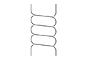
6.5 Socket Definition
6.6Radial cable end dimension drawing

Unit: mm
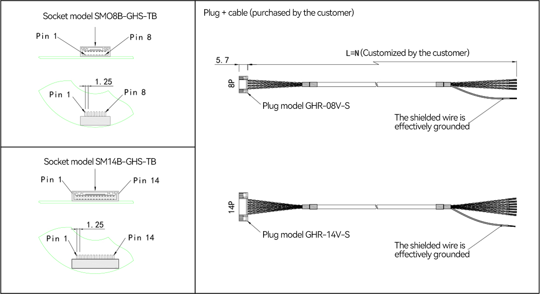
7. Basic dimensions
Product Display
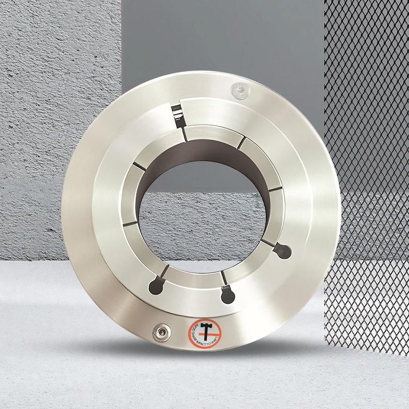
Bearingless split small photoelectric rotary encoder
It features high precision and super thinness
The bearingless design makes installation simple and convenient
High pulse rate and long-lasting durability
It is applicable to a variety of mechanical equipment
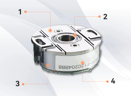
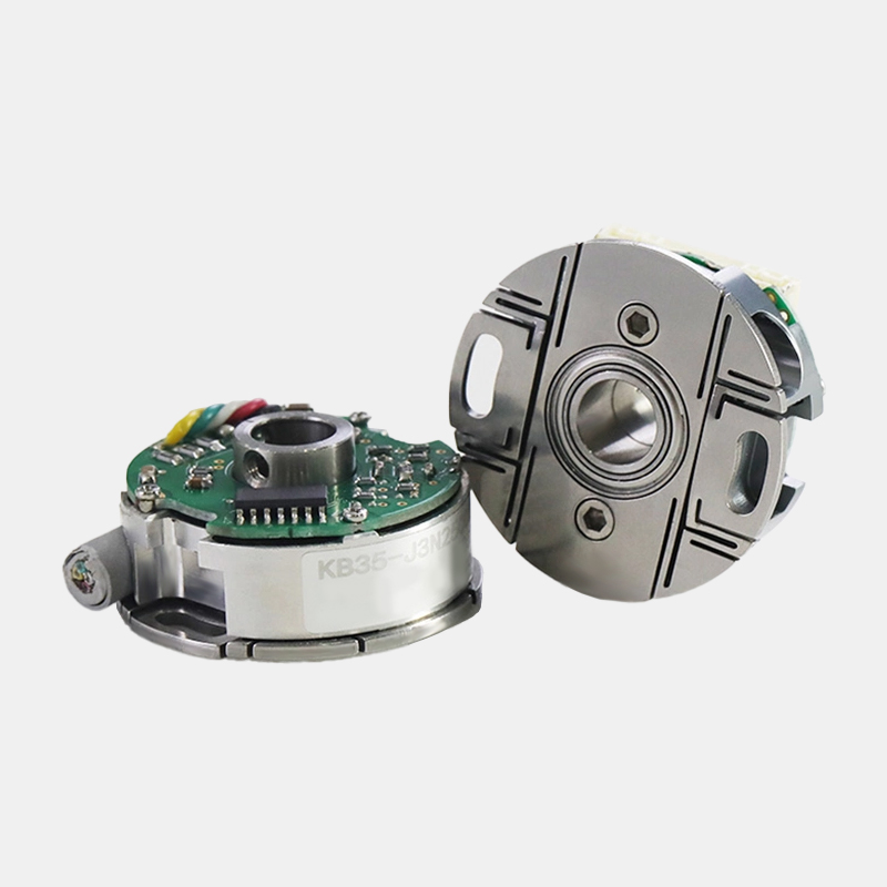
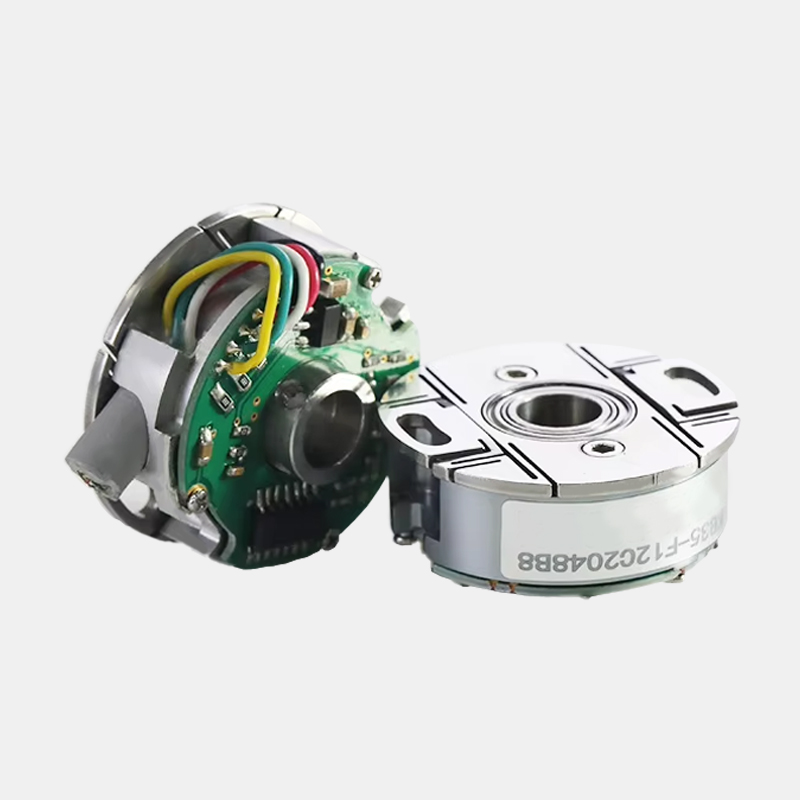
1、Unique mechanical structure
2. Compact and ultra-thin structure design; Shaft concentric locking structure
3. Independently designed grating code disk and assembly process
4. The circuit adopts anti-interference measures
Application Cases
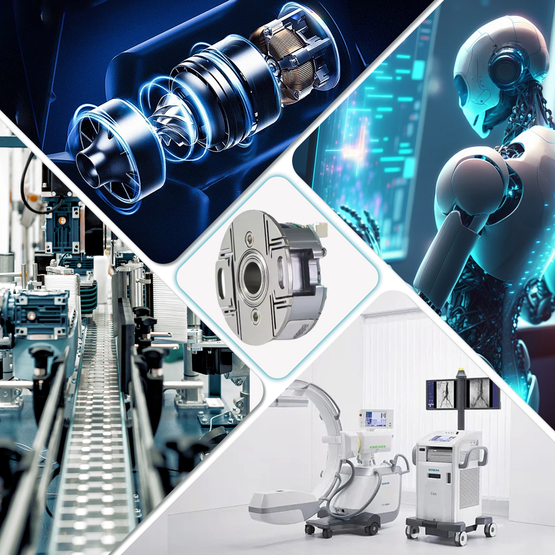
The application scope of KB35 bearingless split-type small photoelectric rotary encoder includes:
In the field of industrial motors: It is applicable to the speed and position detection of electric spindles, DC motors, and servo motors, meeting the requirements of high-speed, high-frequency response, and high-temperature resistance working conditions.
Precision machinery and automation equipment: It can be used for precise control and feedback of machine tools, robots, and automated production lines, adapting to complex industrial environments.
Special scene equipment: such as medical devices that require compact installation and high reliability, aerospace auxiliary machinery, and other scenarios with high precision requirements.
Service
1. Precautions for Using Encoders
A place where the ambient temperature must not exceed the storage temperature; A place where the relative humidity must not exceed the storage
humidity; It cannot be in places with sharp temperature changes and fogging. Places close to corrosive gases and flammable gases; Stay away from
places with a lot of dust, salt and metal powder. Stay away from places where water, oil and medicine are used; Excessive vibration and shock can be
transmitted to the main body
2. Precautions for Installing Encoders
Electrical components must not be subjected to overvoltage or other phenomena. Please conduct static electricity assessment of the setting
environment, etc. Do not allow the motor power line to approach the encoder. The FG wire of the motor and the FG wire of the mechanical device
must be reliably grounded. Since the shielded wire is not connected to the encoder body, the shielded wire must be effectively connected to the
ground at the user end
3. Precautions on Wiring
When used at the specified power supply voltage, please pay attention to the decrease in power supply voltage amplitude caused by the long wiring.
Please do not use the encoder line and other power lines in the same pipe or bundle them in parallel. Please use twisted-pair wires for the signal line
and power line of the encoder. Please do not apply excessive force to the wire harness of the encoder, as there is a risk of wire breakage
4. Regarding the warranty of the encoder
Within twelve months of purchasing the products of our company, if any malfunction occurs due to correct use in accordance with the precautions
in the user manual, warning signs, etc., free warranty will be provided.
The following situations will be charged even within the warranty period: (Freight is at your own expense)
①. Faults and damages caused by the user landing during transportation or handling or improper installation;
②. Faults of this product caused by the machine connected to it;
③. Faults and damages caused by fire, salt water, corrosive gases, abnormal voltages, and other natural disasters such as earthquakes, lightning, wind, and floods;
④. Repair, adjustment or modification without the permission of our company (the label is not present or the outer cover is removed by oneself).
⑤. Malfunctions that occur when the user does not follow the usage methods and precautions described in the user manual.
⑥. Except where there are other agreements signed with the client.