
Product Description
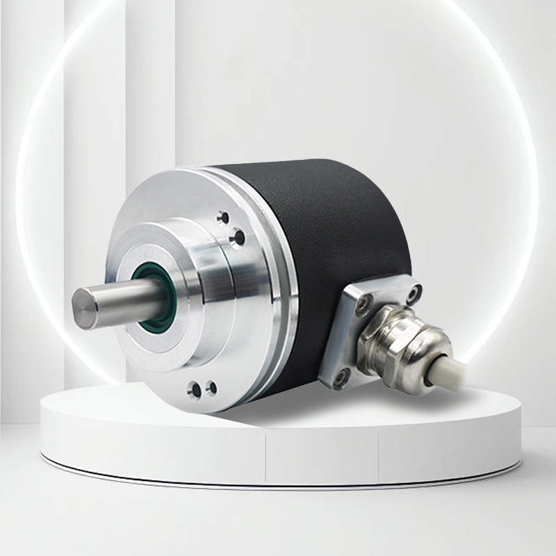
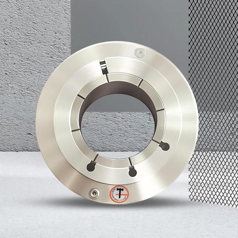
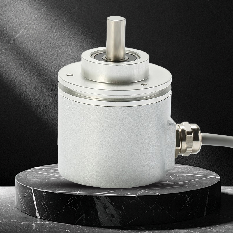
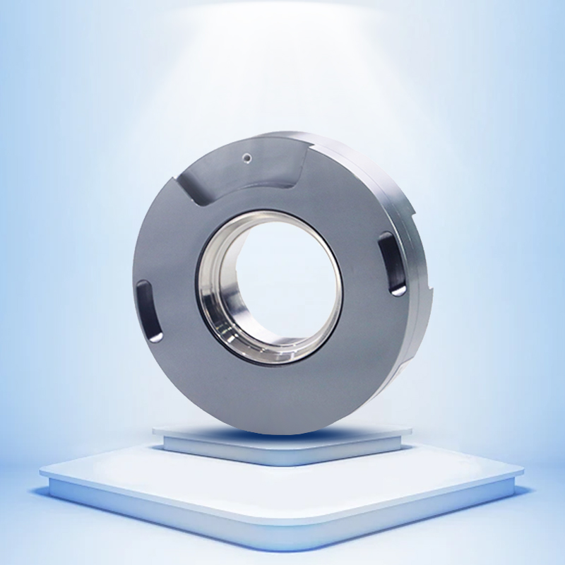
PC58 incremental photoelectric encoder has a unique through-axis concentric locking device, single-bearing ultra-thin design, mechanical hard connection, multiple electrical interfaces, and protection level IP50, which can solve the installation problem of low space restrictions.
Product Features |
|
Product parameters
Project | Parameter | ||||
Dimensions | Outer diameter: 50mm | ||||
Thickness: 30mmm | |||||
Shaft diameter:8mm/10mm/12mm/14mm/15mm | |||||
Pulse | 9;20;30;50;60;100;200;240;250;256;300;360;450;500;512;600;700;800;900;1000;1024;1200;1250;1440; | ||||
Reverse polarity protection | √ | ||||
Short circuit protection | √ | ||||
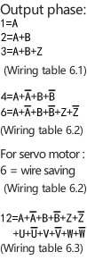
Output phase | Phase A,B,Z,A-,B-,Z- | ||||
Output mode | Radial Cable & Axial Cable | ||||
Protection level | IP50 & IP65 | ||||
Output type | N - Open Collector (NPN) | V - voltage output | F-Push-pull output | TTL | HTL |
Maximum response frequency | 100KHZ | 200KHZ | 300KHZ | ||
Starting torque | 9.8x10⁻³N·m (100gf.cm)or less | ||||
Moment of inertia | 6.5x 10⁻⁶kg·m2 or less | ||||
Axis allowable force | Radial force 40N; axial force 20N | ||||
Maximum allowable speed | <4000rpm;IP65≤3000rpm; | ||||
Ambient temperature | Working: -20 to +90°; Storage: -25 to +95° | ||||
Ambient humidity | 35-85%RH (no condensation) during operation and storage | ||||
Vibration (durability) | Amplitude 0.75mm, 5-55Hz, 2 hours in each of the three axes | ||||
Impact (durability) | 980m/s2 ,11ms,Three times in each direction | ||||
Casing | Die-cast aluminum alloy | ||||
Line length | 1000mm | ||||
Packing method | Paper Box | ||||
Weight | 200g | ||||
Certificate | CE/ ISO9001 | ||||
Instructions
1. Selection guide
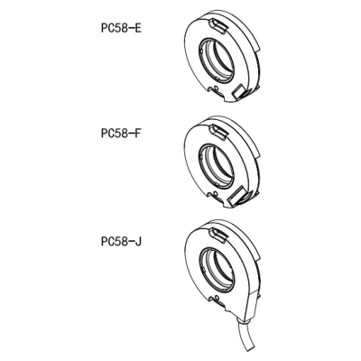
Model composition (selection parameters)
PC58- | E | 6 | S | 2500/8 | Q24 | - | 000 | |||||||||
↑ | ↑ | ↑ | ↑ | ↑ | ↑ | ↑ | ↑ | ↑ | ||||||||
Series | Connection method: |
| Electrical interface: | Resolution PPR: | Shaft diameter: | Supply voltage: | Special requirement: | Management |
Notes:
①Z phase signal is valid at low level.
②Z phase signal is valid at high level.
③None means IP50, cable length is 1M, if you need to change the length, C+number, the maximum length is 100M (indicated by C100)
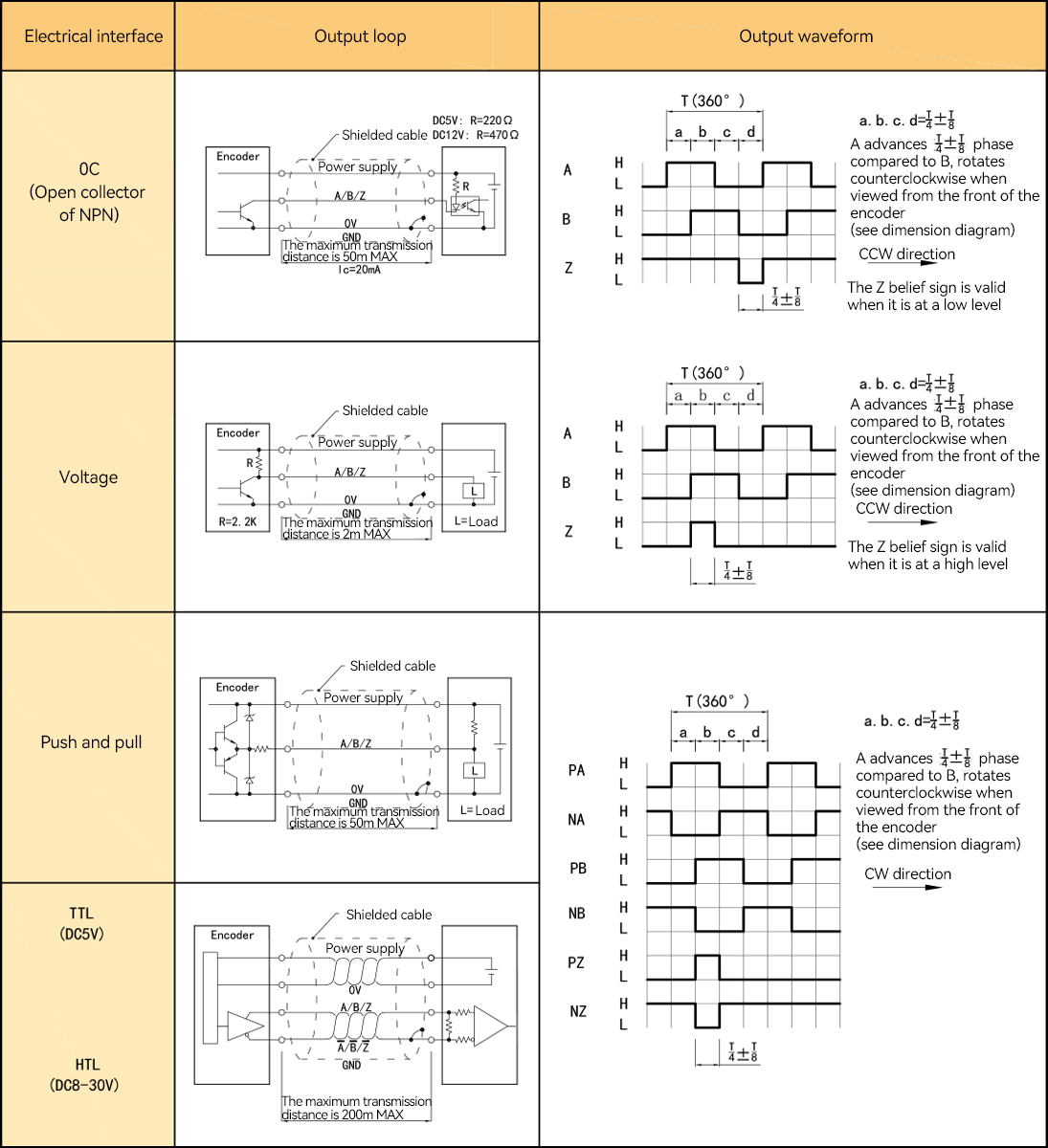
2. Output mode
2.1 Incremental signal
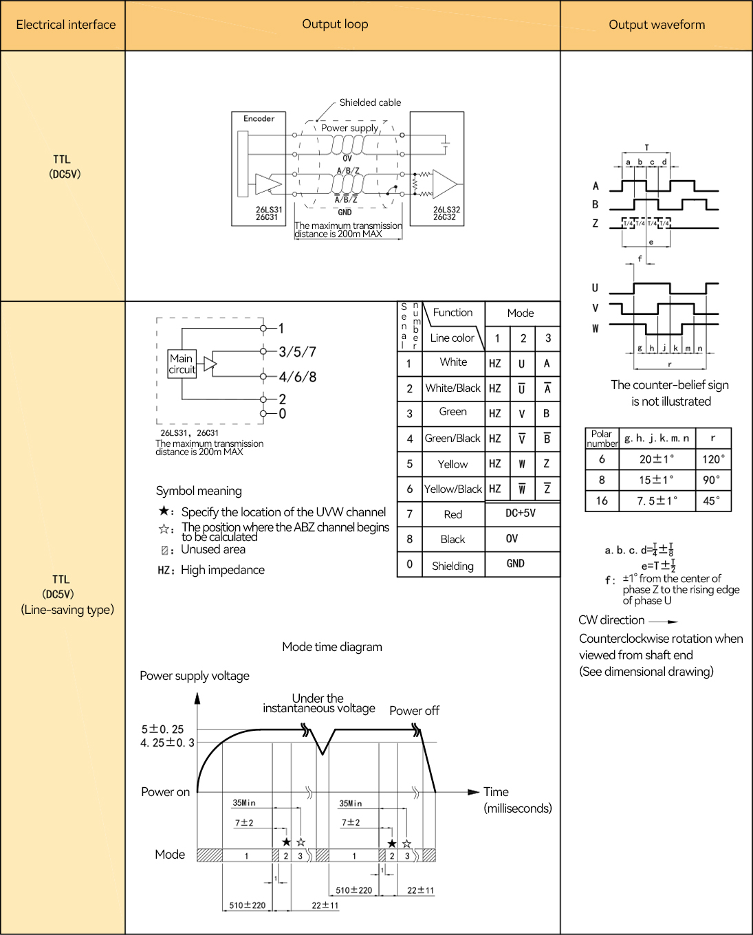
2.2 Dedicated to servo motor (with U.V.W)
Project | Output method | |||||||
OC | Voltage | Push-pull | TTL | HTL | HTL | |||
Supply voltage | DC+5V±5% ; DC8-30V±5% | DC+5V±5% | DC8-30V±5% | |||||
Current consumption | 100mA Max | 120mA Max | ||||||
Allowable ripple | ≤3% rms | |||||||
Maximum response frequency | 100KHz | 300KHz | 500KHz | |||||
Output capacity | Output | Inflow | ≤30mA | Load resistance 2.2K | ≤30mA | ≤±20mA | ≤±50mA | |
Outflow | — | ≤10mA | ||||||
Output | "H" | — | — | ≥[(power supply voltage)-2.5V] | ≥2.5V | ≥Vcc-3 VDC | ||
"L" | ≤0.4V | ≤0.7V(20mA or less) | ≤0.4V(30mA) | ≤0.5V | ≤1 VDC | |||
Load voltage | ≤DC30V | — | — | |||||
Rise and fall time | 2us or less (wire length: 2m) | 1μs or less (wire length: 2m) | ||||||
Insulation withstand voltage | AC500V/60s | |||||||
Insulation impedance | 10MΩ | |||||||
Duty cycle | 45%~55% | |||||||
Reverse polarity protection | ✔ | |||||||
Short circuit protection | — | ✔① | ||||||
A.B Phase Difference | 90°±10° (at low frequency) | |||||||
90°±20° (at high frequency)) | ||||||||
Delay action time ② | — | |||||||
Shielded wire | Encoder body not connected | |||||||
Note: ① Short circuit with another cable or GND, the maximum allowed time is 30 seconds. | ||||||||
4. Mechanical specifications
Project | Parameter |
Shaft diameter | Φ14mm;Φ15mm;Φ19mm;Φ24mm (optional) |
Starting torque | 9.8×10⁻³ N・m or less |
Moment of inertia | 6.5×10⁻⁶ kg・m² or less |
Allowable shaft force | Radial 30N; Axial 10N |
Maximum allowable speed | ≤5000 rpm |
Bearing life | Rated load 1.5×10⁹, 100,000 hours at 2500RPW |
Housing | Base: Die-cast aluminum alloy |
Weight | Approx.100g |
5. Environmental parameters
Project | Parameter |
Ambient temperature | Operating: -20~+85°C (repeated bending cable: -10°C); Storage: -20~+90°C |
Ambient humidity | Operating/Storage: 35~85% RH (non-condensing) |
Vibration (durability) | Amplitude 0.75mm, 5~55Hz, 2h each in three axes |
Shock (durability) | 490m/s², 11ms, 3 times each in X/Y/Z directions |
Protection level | IP50 |
6.1 OC/voltage
Supply voltage | Incremental signal | ||||
Socket pin number | 1 | 2 | 3 | 4 | 5 |
Line color | Red | Black | White | Green | Yellow |
Function | Up | OV | A | B | Z |
6.2TTL/HT L/push-pull/wire saving
Supply voltage | Incremental signal | |||||||
Socket pin number | 1 | 2 | 3 | 4 | 5 | 6 | 7 | 8 |
Line color | Red | Black | White | White / Black | Green | Green/Black | Yellow | Yellow/Black |
Function | Up | OV | A+ | A- | B+ | B- | Z+ | Z- |
Twisted Pair | |  | | | ||||
*For the functional status in wire saving mode, refer to the functional mode wiring table of the output circuit.
6.3 Servo motor only
Supply | Incremental signal | |||||||||||||
Socket pin number | 1 | 2 | 3 | 4 | 5 | 6 | 7 | 8 | 9 | 10 | 11 | 12 | 13 | 14 |
Line color | Red | Black | White | White / | Green | Green/ | Yellow | Yellow/ | Blue | Blue/ | Gray | Gray/ | Pink | Pink/ |
Function | Up | OV | A+ | A- | B+ | B- | Z+ | Z- | U+ | U- | V+ | V- | W+ | W- |
Twisted Pair | | | | | | | | |||||||
Up = power supply voltage.
The shielded wire is not connected to the internal circuit of the encoder.
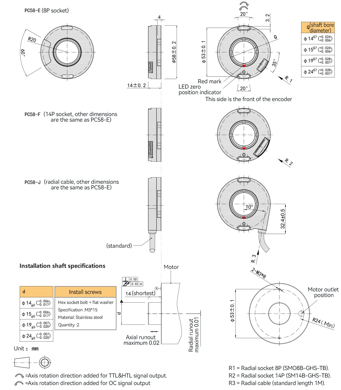
7. Sockets and cables
7.1 Socket pin definition
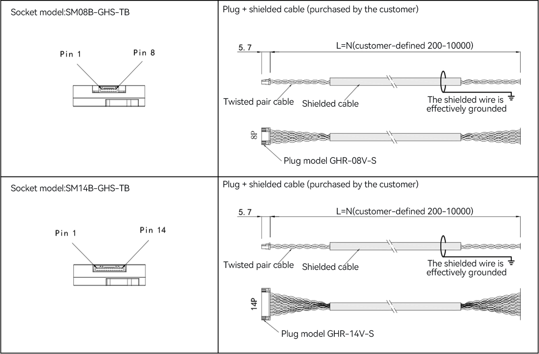
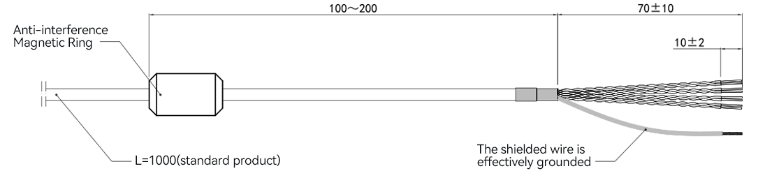
7.2 Radial cable
8. Basic dimensions
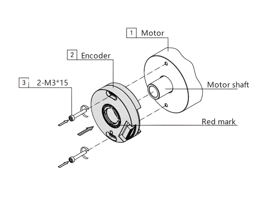
9. Assembly steps for encoders for servo motors 9.1 Installation and zero position alignment of encoders with U.V.W
Step 1 a. Before installing the encoder, first confirm the motor's starting zero position and tighten it to ensure that the motor shaft remains stationary until the encoder is installed. Otherwise, the encoder zero position cannot be aligned with the motor zero position. b. Put the encoder (2) on the motor shaft and gently push it onto the motor platform. c. Screw in the two M3*15 bolts (3) at the same time, but do not tighten them enough to rotate the encoder by hand.
Note: For the tolerance of the encoder sleeve and the motor shaft, please refer to 8. Basic dimensions. |
|
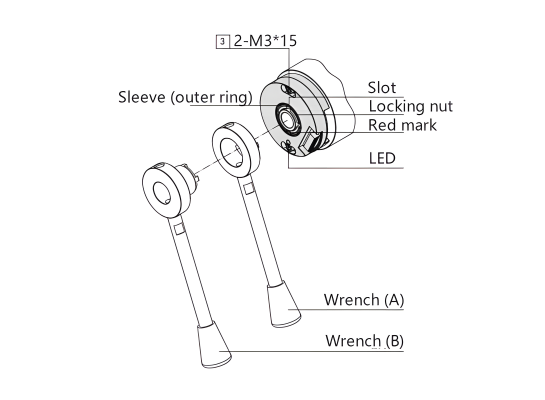
Step 2 a. Put the wrench (A) on the slot of the encoder sleeve (outer ring), and then tighten the lock nut with the wrench (B) (the recommended tightening force is 13-16N.m). b. Connect according to the selected socket wiring table, check and power on. Please confirm again that the motor is in the zero position locked state, then turn the encoder (2) left and right by hand, and observe that the zero position signal is aligned when the LED on the encoder is on. Then tighten the two M3*15 bolts (3) and keep the LED on.
Note: *The red mark on the shaft sleeve always keeps aligned with the LED indicator *After ensuring that the lock nut is tightened, apply thread glue to the thread inside the slot to prevent the thread from loosening. *Because the zero position signal width is relatively narrow, it is easy to cause displacement during the tightening process, making the LED not light up. Please debug patiently or use other visual equipment as an auxiliary observation. |
|
9.2 Incremental encoder installation steps
Step 1 Put the encoder (2) on the shaft of the motor (1), gently push it to the motor platform by hand, and screw in the two M3*15 bolts (3) at the same time and tighten them.
Note: For the matching tolerance between the encoder shaft sleeve and the motor shaft, please refer to 9. Basic dimensions. |
|
Step 2 Put the wrench (A) on the slot of the encoder shaft sleeve (outer ring), and then tighten the lock nut with the wrench (B) to ensure tightening (recommended tightening force is 13-16N.m)
Note: *The red mark on the shaft sleeve is aligned with the LED indicator for the zero position primary position. When the power is turned on and the LED light is on, it is the precise zero position. *After the lock nut is tightened, apply thread glue to the thread in the slot to prevent the thread from loosening. |
|
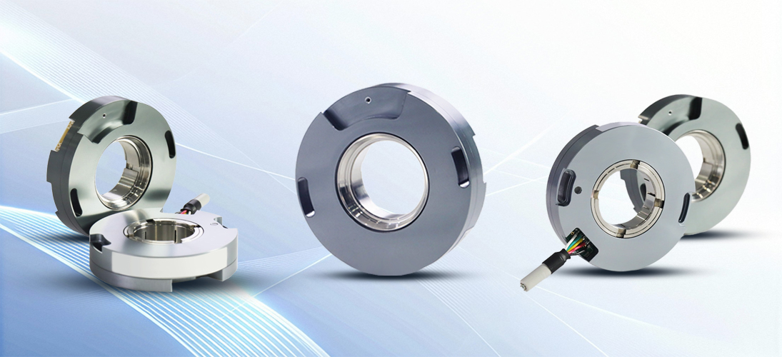
Product Display
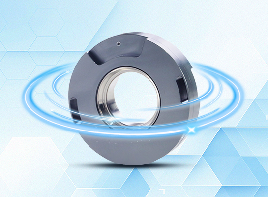
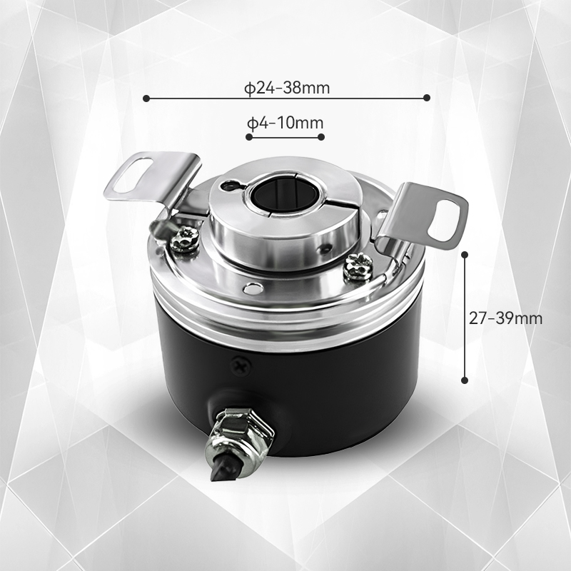
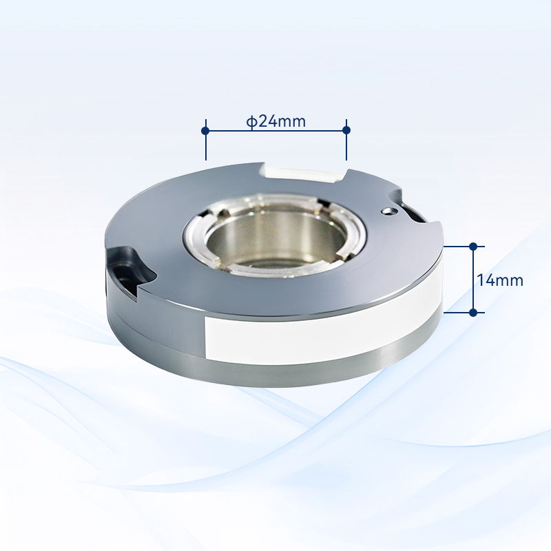
Ultra-thin through-shaft design: only 14mm thick, with concentric locking device, solves the problem of installation in low space
Large shaft diameter compatibility: maximum shaft diameter 24mm, suitable for motor shafts of various specifications
High-precision feedback: up to 5000PPR resolution, non-contact photoelectric principle ensures signal stability
Multiple electrical protections: reverse polarity, short circuit protection, improve system reliability
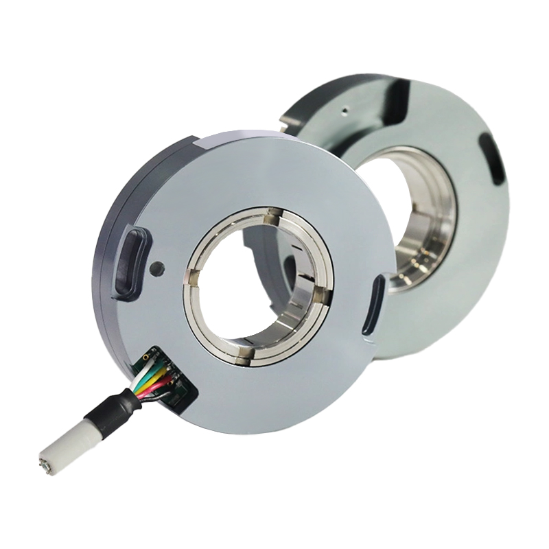
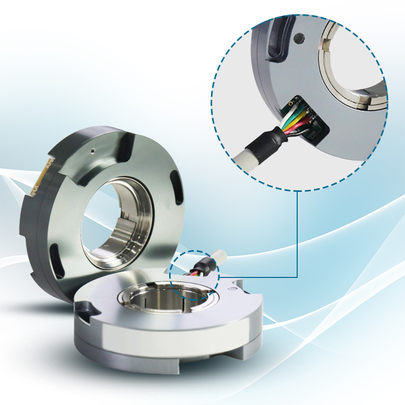
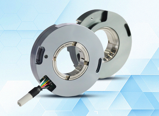
Multi-interface adaptation: supports radial socket (8P/14P) and cable connection, compatible with different control systems
Industrial-grade durability: die-cast aluminum alloy housing, IP50 protection level, adaptable to complex environments
Zero position indication function: LED indicator accurately locates the initial position, easy to debug and calibrate
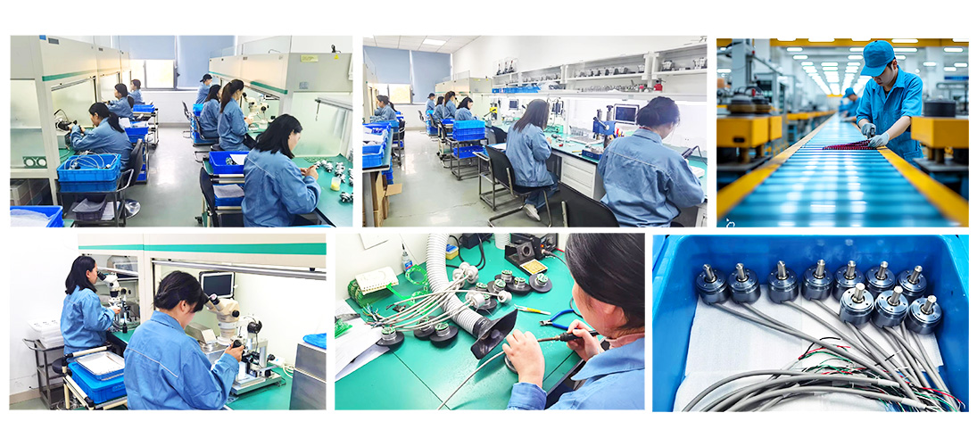
Quality Control
The quality of encoders is directly related to the stability and reliability of industrial automation systems. We have built a full-process quality control system, strictly screening suppliers from raw material procurement to ensure that the performance of core components meets standards; in the production process, we use high-precision equipment and standardized processes, and cooperate with online detection technology for real-time monitoring; in the finished product stage, we conduct rigorous tests such as high and low temperature, electromagnetic compatibility, and life aging to eliminate performance risks. Each encoder has passed multiple quality inspection levels, and its excellent quality has laid a solid foundation for intelligent manufacturing, providing customers with long-term and stable use guarantees.
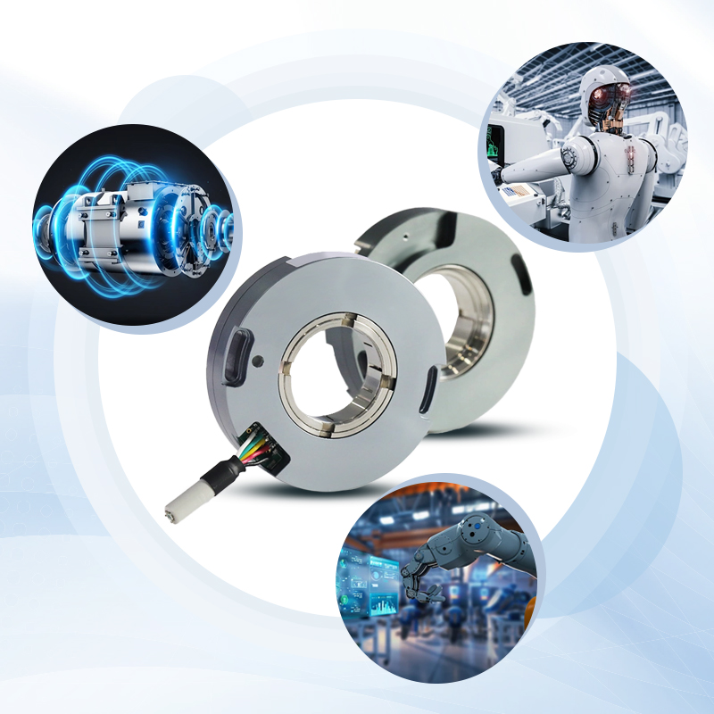
Application Cases
The PC58 series encoders rely on a through-shaft concentric locking device and a single-bearing ultra-thin design (thickness is only 14mm). In the field of servo motors, they achieve precise angle feedback through mechanical hard connection and a maximum resolution of 5000PPR. In robot scenarios, a variety of electrical interfaces are compatible with different control systems, and their reverse polarity/short-circuit protection improves equipment stability. The compact structure is especially suitable for installation in low spaces, meeting the miniaturization and high-precision requirements of automation equipment.

Service
I. Precautions for using the encoder
Places where the ambient temperature does not exceed the storage temperature; places where the relative humidity does not exceed the storage humidity; places where the temperature changes sharply and fogging occurs; places close to corrosive gases and flammable gases; places away from dust, salt, and metal powder; places where water, oil, and medicines are used; places where excessive vibration and impact will be transmitted to the body
II. Precautions for installing the encoder
Electrical components must not be subjected to overvoltage and other phenomena. Please conduct an electrostatic assessment of the setting environment, etc. Do not bring the motor power line close to the encoder; the FG line of the motor and the FG of the mechanical device must be reliably grounded; due to shielding The wire is not connected to the encoder body. Please make sure that the shielded wire is effectively connected to the ground at the user end.
III. Precautions on wiring
When used under the specified power supply voltage, please pay attention to the power supply voltage amplitude drop caused by the long wiring; please do not use the encoder wire and other power wires in the same pipe or bundle them in parallel; please use twisted pair wires for the signal wire and power wire of the encoder wire; please do not apply excessive force to the encoder harness, there will be a risk of disconnection
IV. About encoder warranty
Within twelve months after purchasing our company's products, users can get free warranty when they use them correctly according to the instructions,warning signs and other precautions and cause failures.
The following situations will be charged even during the warranty period: (freight is at your own expense)
1. Failures and damages caused by the user falling to the ground during transportation and handling, improper installation;
2. Failures of this product caused by the machine connected to it;
3. Failures and damages caused by fire, salt water, corrosive gas, abnormal voltage and other natural disasters such as earthquakes, thunder, wind, floods, etc.;
4. Repairs, adjustments, and modifications without the permission of our company (labels are not there or the outer cover is disassembled by yourself).
5. Failures that occur when the product is not used in accordance with the instructions and precautions in the instruction manual.
6. Except when other agreements are signed with the customer.