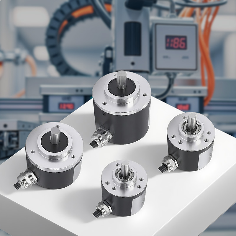
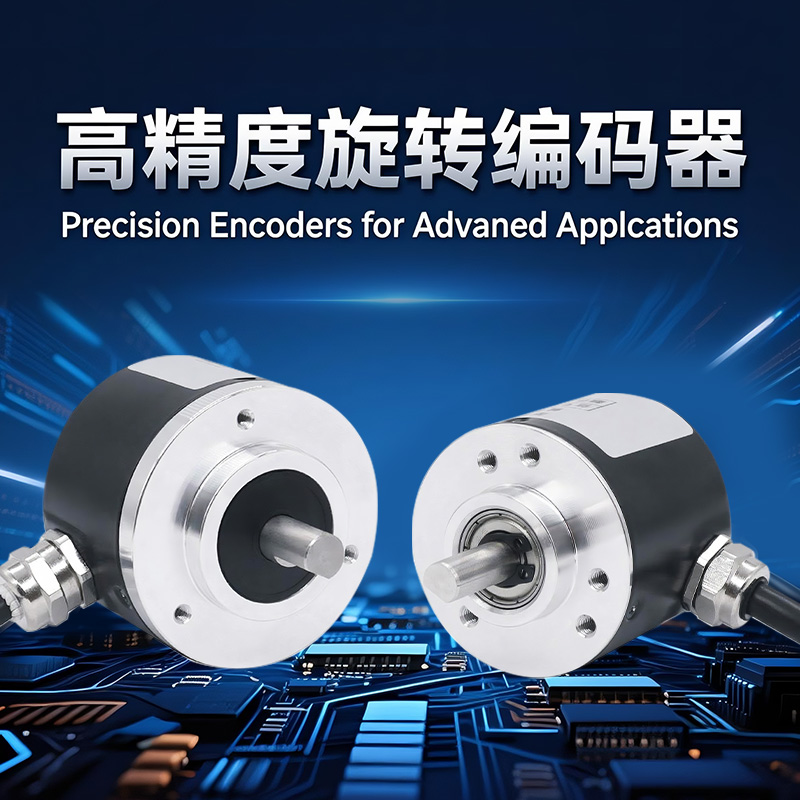
Product Description
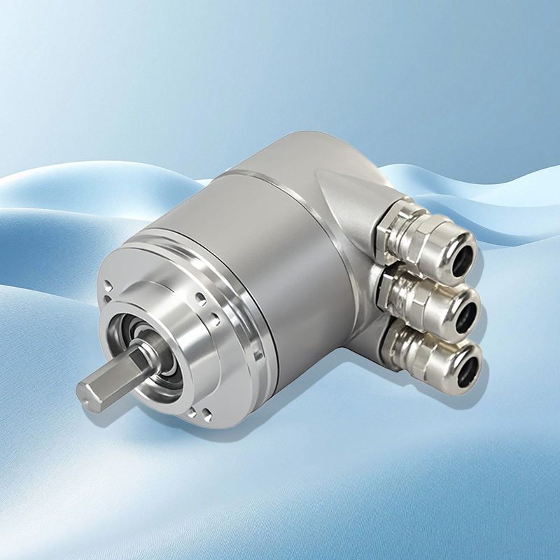
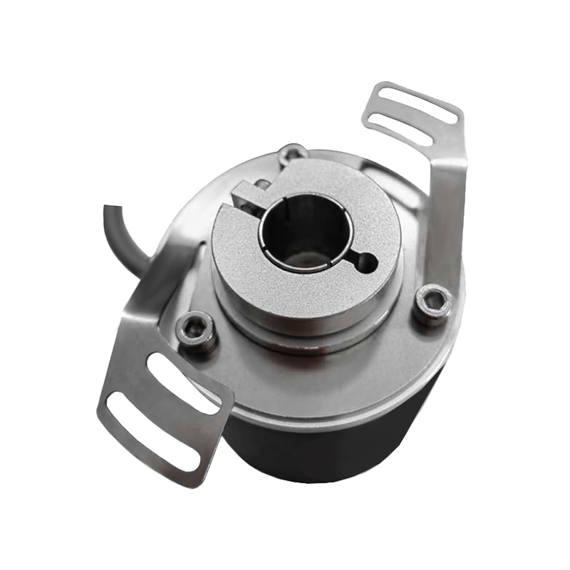
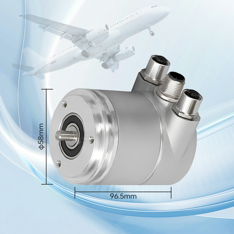
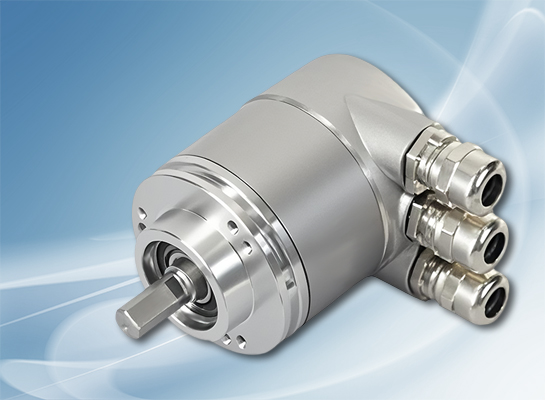
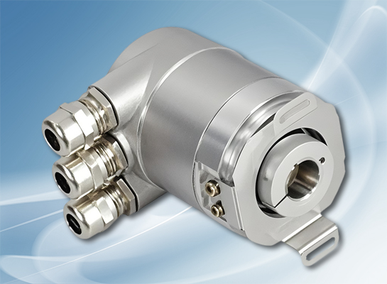
CANopen protocol multi-turn absolute value -58mm outer diameter blind hole type clamping ring encoder
●International standard CANopen protocol;;Maximum 30 people for multiple laps
●Detachable modular bus adapter, with arbitrary address setting;
●European standard installation dimensions, convenient terminal wiring installation; ,
●The highest protection grade reaches IP68, which can be perfectly applied to long-term underwater work.
●The safety lock type bearing design can prevent excessive axial load from causing misalignment.
●Eu explosion-proof grade certification, providing protection for petrochemicals and explosion-proof equipment.
Product parameters

Product series | SASM58J | SASM58T | SASM58H |
Size (Shell) | Ø58mm | ||
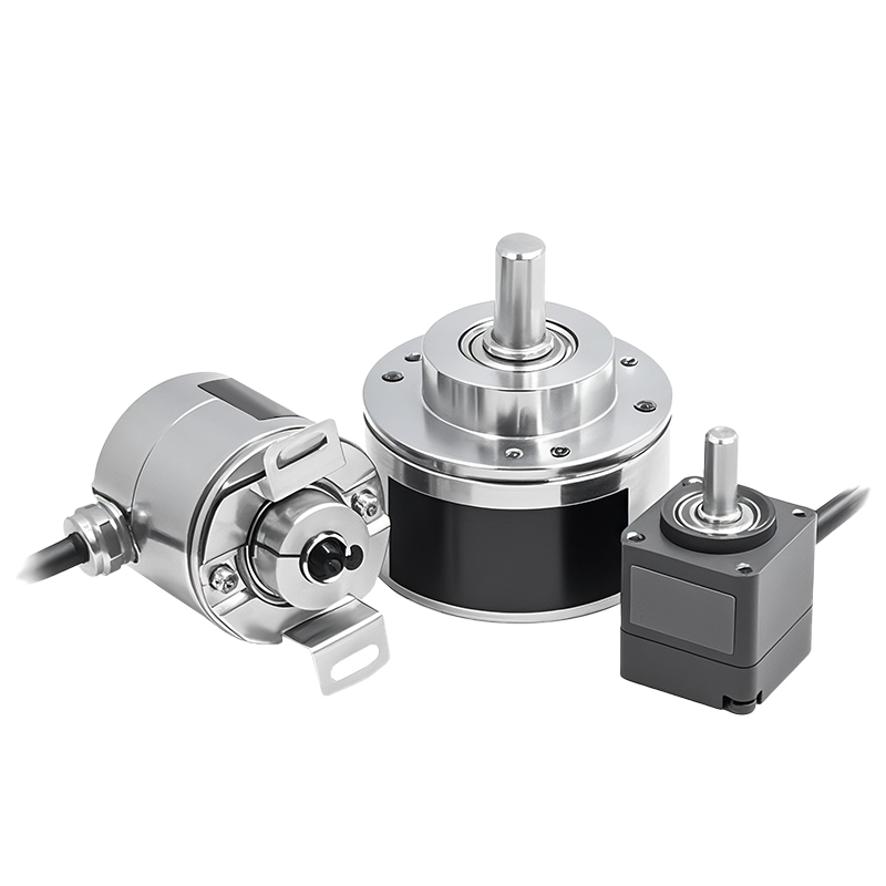
Characteristics | Shaft type with clamping flange | Shaft type with synchronous flange | Hugging ring type blind hole type |
Spindle size | Shaft type Ø6,8,10,12,14,15mm | Shaft type Ø6,8,10mm | Blind hole type Ø6,8,10,12,14,15mm |
Output signal | The international standard CANopen protocol is available for selection | ||
Power supply voltage | 10... 30VDC(Reverse polarity protection, overvoltage protection) | ||
Single-circle resolution | Standard 13-bit 8192, maximum 16-bit 65536 | ||
Number of laps | 4096 laps | ||
Coding | Binary code | ||
Repetition accuracy | ±2BIT | ||
Consumed current | <50mA(24V power supply) no-load | ||
Programmable parameters | The corresponding value for each circle is adjustable. Software limit switch, rotation direction, preset value, rate output, rate time base, baud rate | ||
Maximum rotational speed | 6000r/min | ||
Main shaft load | Radial: 110N, axial: 40N | ||
Protection grade | IP65 or IP66 | ||
Starting torque | ≤3Ncm | ||
Working temperature | - 40 °...85℃(Customizable working temperature -40°...) 85 ℃) | ||
Storage temperature | - 40...100 ℃ | ||
Impact-resistant | 1000m/s²,6ms(100g) | ||
Anti-vibration | 20g | ||
Connection method | Three-hole adapter terminal wiring | ||
Qualification method | Radial lateral protrusion | ||
Programmable parameters | |
Operating parameters | The counting direction can be defined by the operation parameter, which determines the counting direction and whether the output code increases or decreases. |
Single-circle resolution | The resolution parameter can be programmed, and the resolution per revolution can be set as needed. |
Total resolution | This parameter value corresponds to the position value corresponding to the entire measurement length. It cannot exceed the total resolution of the absolute encoder. In the normal mode, the settable value can only be a multiple of 2. |
Preset value | This function is used to set the actual value of the absolute encoder to the desired position value. |
Limit switch, minimum/maximum | Two positions can be programmed. If the measured value exceeds the range between these two values, the encoder will raise one of the 32 positions. |
Programmable transmission mode | |
Query mode | The host acquires the current position data by remotely transmitting communication instructions. The absolute encoder reads out the current position, calculates based on the set parameters, and then communicates Return the actual value through the same CAN recognition unit. |
Circular mode | The absolute encoder cyclically transmits the current actual value without the need for instructions from the host. This cycle time can be programmed and rewritten, ranging from 1 to 65536ms Between, at the millisecond level. |
Synchronous mode | After the controller receives the synchronization signal, the encoder starts to transmit the current actual value. If multiple nodes respond to the synchronization signal, each node responds one by one according to the CAN identifier. Without a programmable compensation time, the synchronization counter can be programmed until a definite number of synchronization signals is reached The coder just transmits. |
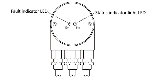
Configuration with connecting caps | LED indicator light | |||||||||
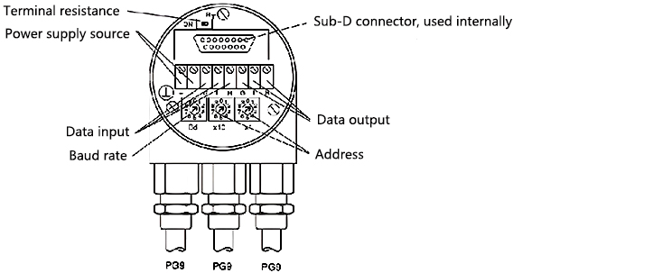
When setting, remove the two screws to open the connecting cap. | There are two leds on the back of the connecting cap, which can display the status of the device. It is very helpful when installing and setting up the encoder. | |||||||||
| ||||||||||
| ||||||||||
Baud rate | ||||||||||
Baud rate | Switch position Baud rate | Switch position | ||||||||
20 | 0 500 | 5 | ||||||||
50 | 1 800 | 6 | ||||||||
100 | 2 1000 | 7 | ||||||||
125 | 3 Retain | 8 | LED red | LED green | Meaning | |||||
250 | 4 Set the SDO and LSS modes | 9 | dark | dark | No power supply | |||||
Node address | dark | bright | The encoder is ready, but the startup message has not been transmitted. Possible reasons: no other slave stations, baud rate error, the encoder is in the ready state | |||||||
flash | bright | The flashing startup message has been transmitted and the device can be configured | ||||||||
bright | bright | In the normal working mode, the encoder is in operation | ||||||||
Settings | Electrical interface | |||||||||
The factory standard configuration of the encoder is as follows: the node address is 32, the baud rate is 20KBaud, and the data transmission cycle time is 0ms(i.e., no cycle). For different applications, customers can make Settings using SDO messages. The effective baud rate ranges from 20kBaud to 1MBaud, the node number is from 0 to 89, and the cycle time is from 1ms to 65536ms. | The absolute rotary encoder with cable and plug interfaces is designed in accordance with the standardized CiADR303-1 cable and plug protocol. There are various electrical connection methods available, such as a 5-pin M12 plug. Encoders can be connected in the following ways: | |||||||||
Electrical signal wiring table for plugs/cables: | ||||
Connection plan | ||||
Function | Wire end | Connector Pin RJ45 | Connector Pin M12 | |
Can High | white | 1 | 4 | |
Can Low | brown | 2 | 5 | |
Can-GND | green | 3 | 1 | |
GND | yellow | 4 | 3 | |
+Ub=10-30V | red | 8 | 2 | |
Install the connecting cap | ||||
The rotary encoder is connected to two or three cables, depending on whether the power supply is integrated into the bus cable or connected separately. If the power supply is integrated into the bus cable, the cable sealing sleeve therein can be installed through a plug. Cable sealing sleeves are suitable for cables with diameters ranging from 6.5 to 9mm. | ||||
| ||||
Function Number | Description | |||
⟂ | Grounding | |||
+ | 10... 30V power supply | |||
- | 0V power supply | |||
Left G | CAN grounding (bus input) | |||
Left L | CAN low (bus input) | |||
Right G | CAN grounding (bus outlet) | |||
Right L | CAN low (bus output) | |||
Right H | CAN high (bus output) | |||
Order model code: | 1 | 2 | 3 | 4 | 5 | 6 | 7 | 8 | 9 | |||
Absolute value encoder | SASM58J | - | XXX | XXX | XX | -XXX | X | -X | XX | -XX | ||
1. Specification series | ||||||||||||
SASM58J | - | |||||||||||
SASM58T | - | |||||||||||
SASM58H | - | |||||||||||
2. Output signal | ||||||||||||
CA CANopen output | CA | |||||||||||
3. Number of rotations | ||||||||||||
B12 12bit(Standard 4096 laps) | B12 | |||||||||||
4. Resolution per circle | ||||||||||||
12 12-bit (4096 resolution) standard product | 12 | |||||||||||
13 13 bit(8192 resolution) | 13 | |||||||||||
14 14 bits (16384 resolution) | 14 | |||||||||||
16 16-bit (65536 resolution) | 16 | |||||||||||
5. Mechanical installation dimensions | ||||||||||||
For details, please refer to the mechanical dimension drawing and order code of the SASM58 multi-turn absolute encoder | ||||||||||||
6. Protection level, housing material | ||||||||||||
0 Protection grade: IP65, aluminum alloy casing | 0 | |||||||||||
S protection grade IP68, aluminum alloy shell (can work underwater for a long time) | S | |||||||||||
V Protection grade IP66, stainless steel heavy-duty housing | V | |||||||||||
W Protection grade IP68, stainless steel heavy-duty housing (can work underwater for a long time) | W | |||||||||||
H Protection grade IP66, aluminum alloy shell (military-grade low-temperature standard -40°C) | H | |||||||||||
7. Qualification method | ||||||||||||
A The A-axis protrudes backward | A | |||||||||||
R exits radially and laterally | R | |||||||||||
8. Connection form | ||||||||||||
A1 cable Ø6.8mm, 8x2x0.35mm ², 1m (Length customizable) | A1 | |||||||||||
AC 8-pin AC plug | AC | |||||||||||
AB plug 12-pin M23 | AB | |||||||||||
9. EX explosion-proof type | ||||||||||||
EX explosion-proof encoder EX II 2G Ex ib IIB T4 Gb | EX | |||||||||||
Dimension installation drawing
SASM58J Dimension Drawing:

SASM58T Dimension Drawing:

SASM58H Dimension Drawing:

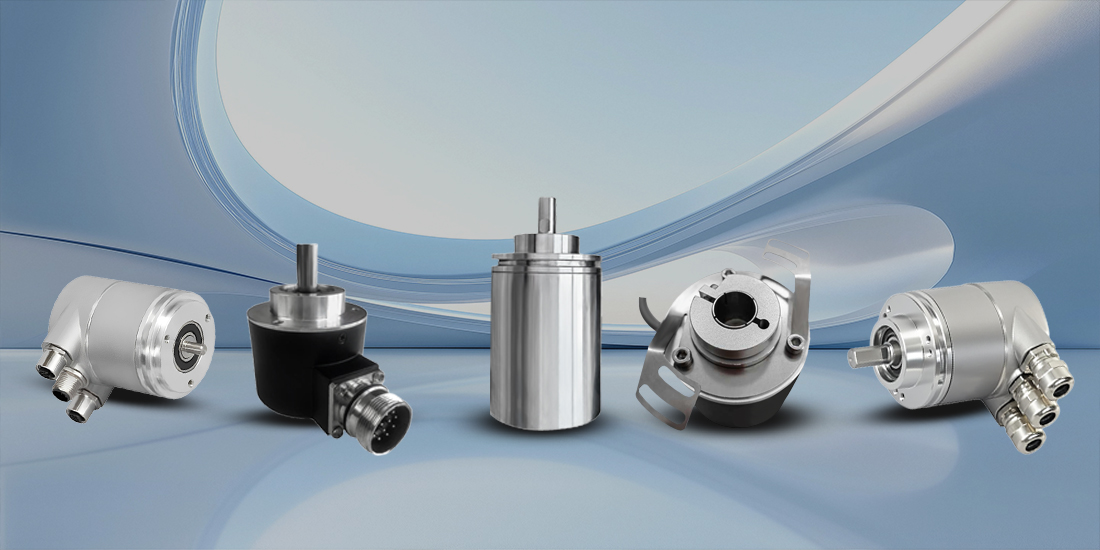
Product Display
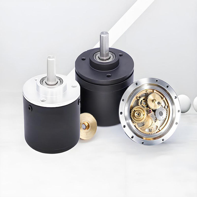
Multi-turn encoder
Full-range absolute position feedback
High precision and high reliability
Rich communication protocols
Long service life and maintenance-free
Flexible adaptability
Single-turn encoder
High-precision single-turn positioning
Compact and easy-to-install design
Multi-signal output
High-efficiency anti-interference performance
High cost performance and universal applicability
Application Cases
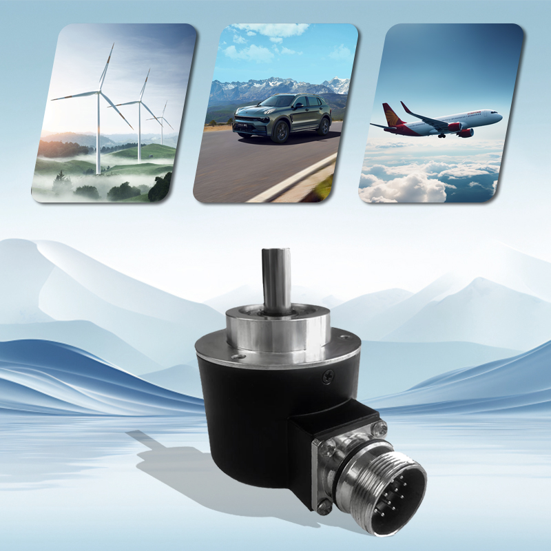
This product is involved in industries and projects such as ports, lifting, shipping, mining, water conservancy, steel and metallurgy, petrochemicals, stone, energy, food processing, aerospace, automobiles, papermaking and printing, injection molding, textiles, packaging, military industry, elevators, machine tools, etc.

Service
1. Precautions for Using Encoders
A place where the ambient temperature must not exceed the storage temperature; A place where the relative humidity must not exceed the storage
humidity; It cannot be in places with sharp temperature changes and fogging. Places close to corrosive gases and flammable gases; Stay away from
places with a lot of dust, salt and metal powder. Stay away from places where water, oil and medicine are used; Excessive vibration and shock can be
transmitted to the main body
2. Precautions for Installing Encoders
Electrical components must not be subjected to overvoltage or other phenomena. Please conduct static electricity assessment of the setting
environment, etc. Do not allow the motor power line to approach the encoder. The FG wire of the motor and the FG wire of the mechanical device
must be reliably grounded. Since the shielded wire is not connected to the encoder body, the shielded wire must be effectively connected to the
ground at the user end
3. Precautions on Wiring
When used at the specified power supply voltage, please pay attention to the decrease in power supply voltage amplitude caused by the long wiring.
Please do not use the encoder line and other power lines in the same pipe or bundle them in parallel. Please use twisted-pair wires for the signal line
and power line of the encoder. Please do not apply excessive force to the wire harness of the encoder, as there is a risk of wire breakage
4. Regarding the warranty of the encoder
Within twelve months of purchasing the products of our company, if any malfunction occurs due to correct use in accordance with the precautions
in the user manual, warning signs, etc., free warranty will be provided.
The following situations will be charged even within the warranty period: (Freight is at your own expense)
①. Faults and damages caused by the user landing during transportation or handling or improper installation;
②. Faults of this product caused by the machine connected to it;
③. Faults and damages caused by fire, salt water, corrosive gases, abnormal voltages, and other natural disasters such as earthquakes, lightning, wind, and floods;
④. Repair, adjustment or modification without the permission of our company (the label is not present or the outer cover is removed by oneself).
⑤. Malfunctions that occur when the user does not follow the usage methods and precautions described in the user manual.
⑥. Except where there are other agreements signed with the client.


