How are tracked chassis designed?
I. Introduction to Tracked Chassis
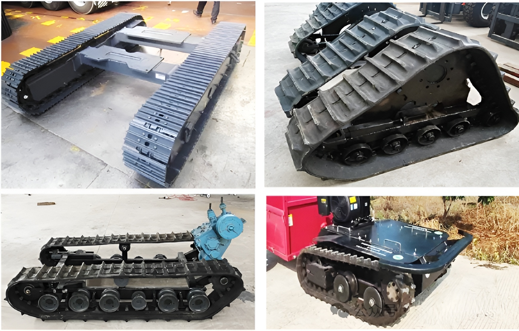
Traction chassis can be classified by structure into wheeled, tracked, half-tracked, and biomimetic types. Tracked chassis are further divided into standard, inverted trapezoidal, triangular, and combined types. Standard chassis have a long ground contact length, low center of gravity, and good stability; inverted trapezoidal chassis have high walking speed and good passability; triangular chassis have large ground clearance and good stability, preventing tipping, but have a complex structure and high cost; combined chassis have better passability than standard chassis and better stability than inverted trapezoidal chassis.
Tracked chassis can be divided into metal tracks and rubber tracks based on materials. Metal tracks have high structural strength, rigidity, traction, and load-bearing capacity, but are more damaging to sandy roads; rubber tracks have low walking resistance, are lightweight, corrosion-resistant, and have low vibration, and are widely used in small agricultural and forestry machinery.
II. Tracked Chassis Parameters and Calculations
1. Track Pitch
The relationship between track pitch and chassis weight can be calculated using the following formula:

Where: t0 is the track pitch, mm; M is the chassis mass, kg.
2. Track Ground Contact Length, Gauge, and Track Width
The ratio of track ground contact length L to track gauge B has a significant impact on the chassis's steering and stability, and the ratio L/B should be between 1.2 and 1.5.
The track width b is generally calculated using the following formula:

3. Ground Contact Pressure
The track ground contact pressure determines the chassis's passability and is an important basis for the overall design of tracked vehicles. It is determined by chassis weight, ground contact length, and track width. It can generally be calculated using the following formula:
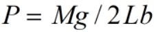
Where: M is chassis weight, kg; g is gravitational acceleration; P is ground contact pressure, kPa; L is track ground contact length; b is track width, m.
III. Tracked Chassis Wheel System Design
1. Drive Wheel
The number of teeth on the drive wheel is generally chosen to be coprime to the number of track links, and each track plate spans two teeth on the drive wheel during engagement. Power is transmitted to the track through the meshing of the wheel teeth and track link pins, generating the power to drive the chassis. Therefore, the drive wheel should be able to mesh smoothly with the track and have good meshing capability.

Where: D is the diameter of the drive wheel, and n is the number of teeth on the drive wheel.
2. Track Roller
The function of the track roller is to support the chassis and transfer the weight of the chassis to the ground through the track, preventing the track from derailing due to lateral slippage. Therefore, the smaller the diameter of the track roller and the more numerous the track rollers, the more even the pressure of the track on the ground.

3. Carrier Roller
The function of the carrier roller is to reduce the sag of the track when the chassis moves. Its diameter is slightly smaller than that of the track roller.
IV. Power Calculation of Tracked Chassis
1. Track Friction Resistance
Track travel resistance includes internal and external resistance. Internal resistance mainly consists of friction generated within the support rollers, bearings, and seals during drive wheel rotation, as well as the roller friction on the track. Generally, external resistance is the main component of travel resistance, with an internal friction resistance coefficient of 0.05~0.10.
2. Chassis Travel Power
During travel, a tracked chassis needs to overcome rolling resistance from the road surface, internal friction resistance, air resistance, slope resistance during climbing, acceleration resistance during acceleration, and the supporting force of the ground on the chassis.

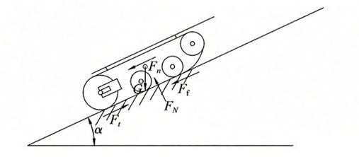
1) Rolling resistance is the tangential force exerted by the ground on the tracks during chassis travel. The main influencing factor is the self-weight of the tracked chassis. According to force analysis:
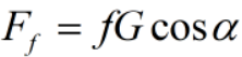
Where: α is the travel slope, f is the road rolling resistance coefficient, and G is the weight of the chassis when fully loaded.
2) Internal friction resistance mainly originates from the rolling friction between each wheel system and the track. Generally:
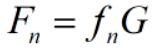
Where: is the internal friction coefficient, generally taken as 0.04~0.08.
3) The power P required for chassis movement can generally be calculated using the following formula:
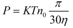
Where: P is the power required for chassis movement, kW; K is the safety factor, taken as 1.3; T is the torque required by the motor, Nm; n0 is the speed of the drive wheel, r/min; η is the transmission efficiency, taken as 0.9.
V. Chassis Stability and Passability
1. Chassis Slope Stability Analysis
The slope of hilly and mountainous areas in my country is approximately 0°~30°. When the slope is greater than 25°, it is not suitable for planting crops.
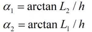
The longitudinal limit overturning angle of the tracked chassis can be calculated using the following formula:
Where: L1 is the distance from the chassis center of gravity to the rear support point, L2 is the distance from the chassis center of gravity to the front support point, and h is the height of the chassis center of gravity above the ground.
Based on the force analysis above, the condition for the chassis to not slip is:
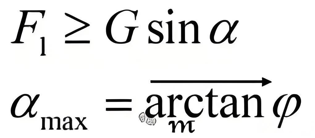
Where: F1 is the longitudinal adhesion force to the ground, G is the weight of the tracked chassis, μ is the maximum slope angle, and φ is the chassis adhesion coefficient, taken as 0.42.
2. Chassis Lateral Stability Analysis
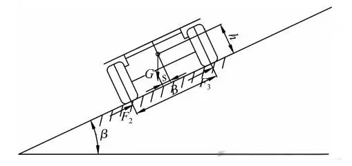
When the tracked chassis travels on a transverse slope, if the slope angle is greater than the critical overturning angle, the vehicle will overturn or slip laterally. When the chassis overturns, the reaction force on the right side is zero.
The maximum slip angle for the chassis to park on a transverse slope without slipping is β. According to the force analysis,
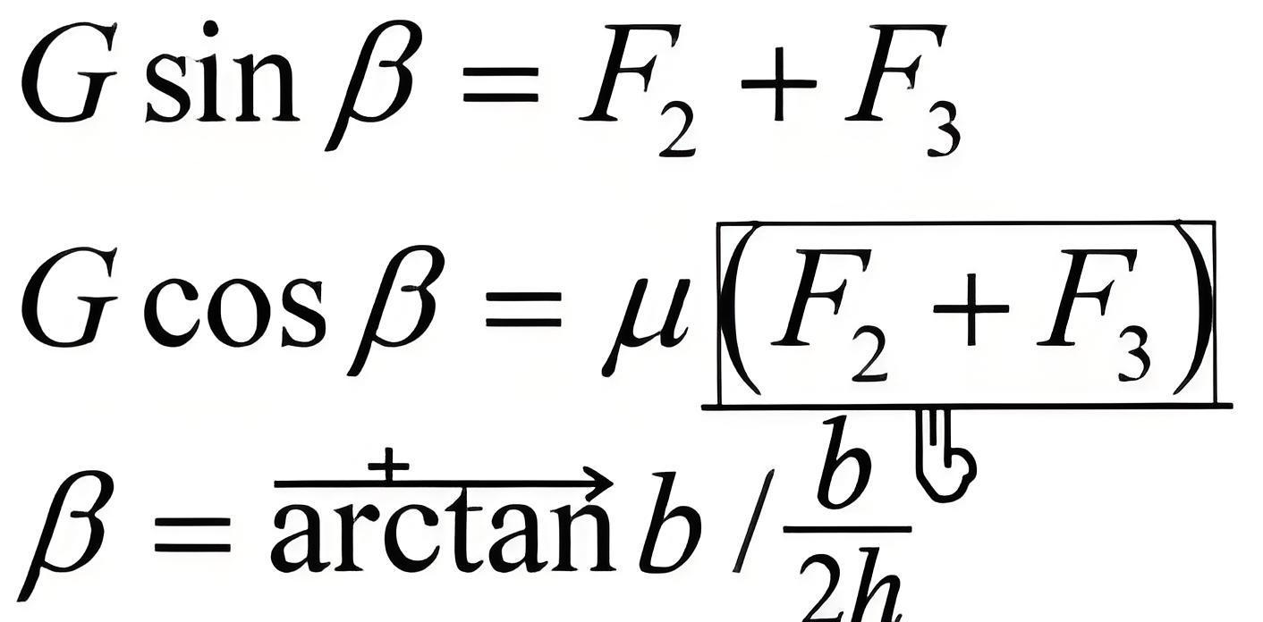
Based on the force analysis above, the condition for the chassis to not slip is:
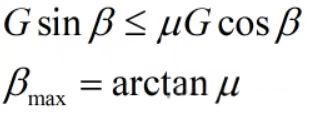
Where: b is the track width, μ is the ground adhesion coefficient, taken as 0.67, F2 is the lateral ground adhesion force of the left track, and F3 is the lateral ground adhesion force of the right track.
3. Chassis Crossing Grooves Analysis
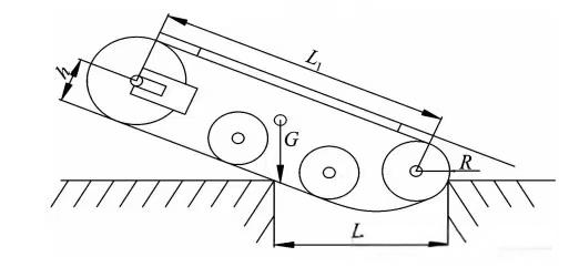
The width of a chassis crossing a groove is related to the contact length between the track and the ground and the position of the center of gravity. A static method can be used to analyze and determine whether the chassis can cross the groove. It is mainly determined by the distance between the support points at both ends of the chassis and the projection of the center of gravity onto the driving plane.

4. Chassis Crossing Obstacles Analysis
When the tracked chassis enters obstacle-crossing mode, the chassis climbs to the maximum vertical obstacle height. At this point, because the vertical line of the center of gravity coincides with the edge of the vertical obstacle, the chassis, under the action of gravity, passes the point of coincidence of the obstacle on the vertical line of gravity. Continuing forward, the rear drive wheel leaves the ground, and the front wheel rotates clockwise and lands at the top of the obstacle. Analysis shows that the relationship between the vertical obstacle height and the tracked chassis structural parameters can be referenced by the following formula:

Where: H is the vertical obstacle height, h is the center of gravity height, θ is the chassis climbing angle, d is the distance between the centers of the tension wheel and the drive wheel perpendicular to the chassis, and θ is the radius of the tension wheel.
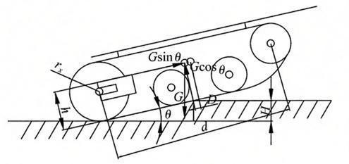
As can be seen from the above formula, the position of the chassis center of gravity and the height of the center of gravity affect the obstacle clearance height. The higher the center of gravity, the more unfavorable it is for obstacle clearance.
Source: Online Public Resources