How to Make a Robot - Lesson 5: Choosing a Motor Controller
Step 1 — Lessons Menu
Lesson 1 – Getting Started
Lesson 2 - Choosing a Robotic Platform
Lesson 3 - Making Sense of Actuators
Lesson 4 - Understanding Microcontrollers
Lesson 5 - Choosing a Motor Controller
Lesson 6 – Controlling your Robot
Lesson 7 - Using Sensors
Lesson 8 - Getting the Right Tools
Lesson 9 - Assembling a Robot
Lesson 10 - Programming a Robot
Now that the general shape, the actuators (or motors), and the brain for the robot have been chosen, it is time to make things move. The first question many beginners have when building their first robot is "how do I control the motors?" After a bit of research, the word motor controller comes up a lot.
Step 2 — What is a motor controller and why do I need it?
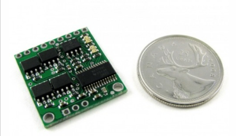
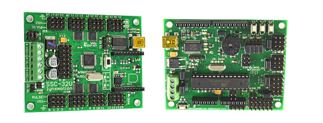
A motor controller is an electronic device (usually comes in the shape of a bare circuit board without enclosure) that acts as an intermediate device between a microcontroller, a power supply or batteries, and the motors. Although the microcontroller (the robot's brain) decides the speed and direction of the motors, it cannot drive them directly because of its very limited power (current and voltage) output. The motor controller, on the other hand, can provide the current at the required voltage but cannot decide how fast the motor should turn. Thus, the microcontroller and the motor controller have to work together in order to make the motors move appropriately. Usually, the microcontroller can instruct the motor controller on how to power the motors via standard and simple communication methods such as UART (a.k.a. serial) or PWM. Also, some motor controllers can be manually controlled by an analog voltage (usually created with a potentiometer). The physical size and weight of a motor controller can vary significantly, from a device smaller than the tip of your finger used to control a mini sumo robot to a large controller weighing several Kg. The weight and size of a motor controller usually have a minimal impact on the robot, until you get into small robotics or unmanned aerial vehicles. The size of a motor controller is usually related to the maximum current it can provide. A larger current also means having to use larger diameter wires (the smaller the gauge number, the larger the diameter).
Since there are several types of actuators (as discussed in lesson 3), there are several types of motor controllers:
Motor Controller Types
Brushed DC motor controllers: used with brushed DC, DC gear motors, and many linear actuators.
Brushless DC motor controllers: used with brushless DC motors.
Servo Motor Controllers: used for hobby servo motors
Stepper Motor Controllers: used with unipolar or bipolar stepper motors depending on their kind.
Step 3 — Choosing a Motor Controller
Motor controllers can only be chosen after you have selected your motors/actuators. Also, the current a motor draws is related to the torque it can provide: a small DC motor will not consume much current, but cannot provide much torque, whereas a large motor can provide higher torque but will require a higher current to do so.
DC Motor Control
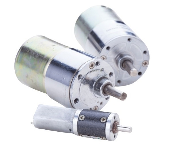
The first consideration is the motor's nominal voltage. DC motor controllers tend to offer a voltage range. For example, if your motor operates at 3V nominal, you should not select a motor controller that can only control a motor between 6V and 9V. This will help you cross off some motor controllers from the list.
Once you have found a range of controllers that can power the motor with the appropriate voltage, the next consideration is the continuous current the controller will need to supply. You need to find a motor controller that will provide current equal to or above the motor's continuous current consumption under load. Should you choose a 5A motor controller for a 3A motor, the motors will only take as much current as they require. On the other hand, a 5A motor is likely to burn a 3A motor controller. Many motor manufacturers provide a DC motor's stall current, which does not give you a clear idea of the motor controller you will need. If you cannot find the motor's continuous operating current, a simple rule of thumb is to estimate the motor's continuous current at about 20% to 25% of the stall current. All DC motor controllers provide a maximum current rating - be certain this rating is about double that of the motor's continuous operating current. Note that when a motor needs to produce more torque (for example going up an incline), it requires more current. Choosing a motor controller with built-in over current and thermal protection is a very good choice.
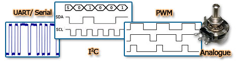
The Control method is another important consideration. Control methods include analog voltage, I2C, PWM, R/C, and UART (a.k.a. serial). If you are using a microcontroller, check to see which pin types you have available and which motors are viable for you to choose. If your microcontroller has serial communication pins, you can choose a serial motor controller; for PWM, you will likely need one PWM channel per motor.
The final consideration is a practical one: Single vs. dual (double) motor controller. A dual DC motor controller can control the speed and direction of two DC motors independently and often saves you money (and time). The motors do not need to be identical, though, for a mobile robot, the drive motors should be identical in most cases. You need to choose the dual motor controller based on the more powerful DC motor. Note that dual motor controllers tend to have only one power input, so if you want to control one motor at 6V and the other at 12V, it will not be possible. Note that the current rating provided is almost always per channel.
Servo Motor Control
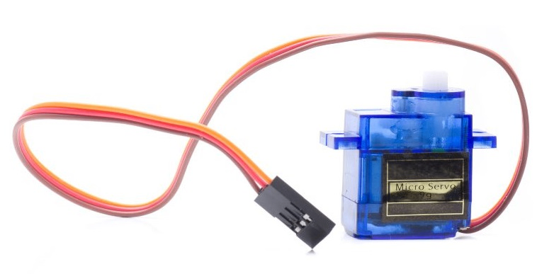
Since standard hobbyist servo motors are meant to use specific voltages (for peak efficiency), most operate at 4.8V to 6V, and their current consumption is similar, the steps for the selection are somewhat simplified. However, you may find a servo motor that operates at 12V; it is important to do additional research about a servo motor controller if your servo motor is not considered "standard". Also, most hobby servo motors use the standard R/C servo input (three wires which are ground, voltage and signal)
Choose the control method. Some servo motor controllers allow you to control the servo's position manually using a dial/switch/buttons, while others communicate using UART (serial) commands or other means.
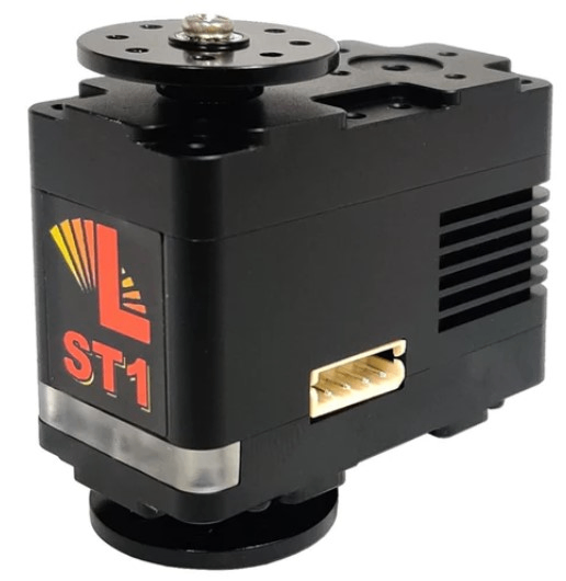
Determine the number of servos to be controlled. Servo controllers can control many servos (usually 8, 16, 32, 64, and up). You can certainly select a servo motor controller capable of controlling more servos than you will need.
As with DC motor controllers, the control method is an important consideration.
Stepper Motor Control
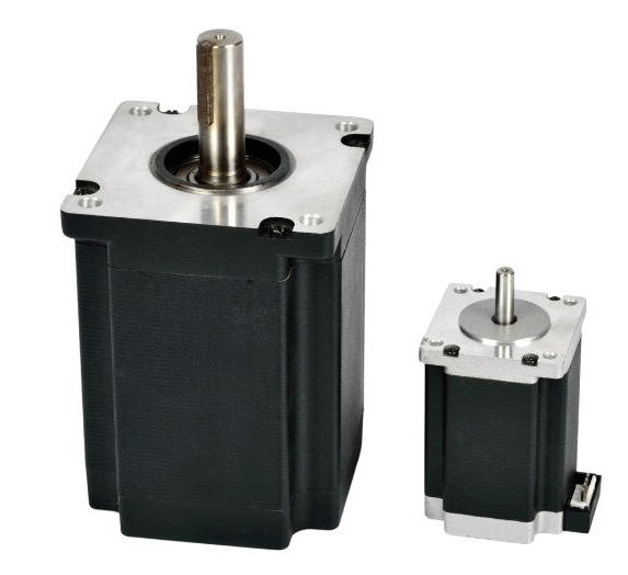
Is the motor you selected unipolar or bipolar? Choose a stepper motor controller type accordingly, though a growing number are able to control both types. The number of leads is usually a dead giveaway of the motor type: if the motor has 4 leads, then it is bipolar; should it have 6 or more leads, then it is unipolar.
Choose the motor controller voltage range to match your motor's nominal voltage.
Find out how much current per coil your motor requires, and find out how much current (per coil) the stepper motor controller can provide.If you cannot find the current per coil, most manufacturers list the coil impedance, R . Using Ohms Law (V=IR), you can then calculate the current (I).
As with DC motor controllers, the control method is an important consideration.
Linear Actuator Control
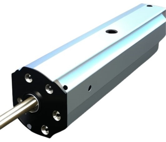
Linear actuators come in three main flavors regarding their control method: DC, R/C, or position feedback. Most DC linear actuators use a geared DC motor, so a DC motor controller is usually appropriate. However, some linear actuators take R/C servo input, so you would select a servo motor controller. Should an R/C-controlled linear actuator operate at a higher voltage than the servo controller's range, the actuator may include separate wires for the higher supply voltage required.
Other Actuators
Many "miscellaneous" electromechanical devices such as muscle-wire, solenoids, or even powerful lights need to be controlled using motor controllers. Below are some questions to determine if your actuator might need a motor controller:
Higher current requirements: any device that requires over 0.1A usually needs its own controller
Higher voltage requirements: if the actuator operates above the microcontroller's voltage (usually 5V or 3.3V), it usually cannot be directly connected to a microcontroller
Step 4 — Practical Example
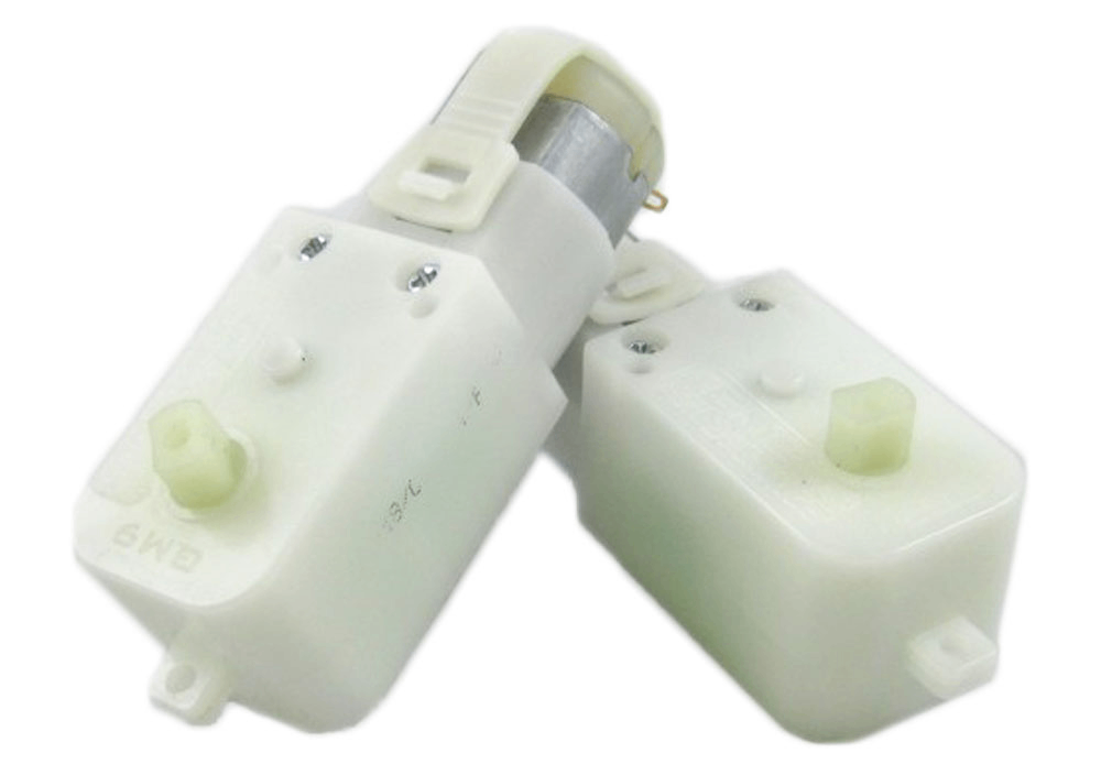
In the previous lesson, we had chosen the Solarbotics GM9 gear motors. Below are this motor’s specifications:
Gear Ratio: 143:1
Unloaded RPM (3V): 40
Unloaded RPM (6V): 78
Unloaded Current (3V): 50mA
Unloaded Current (6V): 52mA
Stall Current (3V): 400mA
Stall Current (6V): 700mA
Stall Torque (3V) : 44.44in*oz
Stall Torque (6V) : 76.38in*oz
Applying the steps:
The nominal voltage is 3V or 6V.
There is no mention of continuous current, though the stall torque at both voltages is provided: 400mA and 700mA. If we take 25% of these values, the continuous current can be approximated at 100mA to 175mA. To be safe we can take the larger value.
We have chosen a microcontroller that has many different pins including serial, PWM, analog, and digital.
Our little rover will be using two identical motors, so we can use a dual-motor controller.
Given the above criteria, we are looking for a motor controller with the following specifications:
Voltage range can accommodate a 3V to 6V motor
Continuous current at least 350mA per channel (low power category)
Communication method is PWM, I2C, or analog (or several of these)
Dual motor control is preferred.
By Looking at the available motors several motor controllers fit the criteria:
RB-Dim-19 (6-18V, 5A, dual. Analogue and Serial interfaces with many safety features)
RB-Pol-16 (1.5-6V, 5A, dual. Low-cost controller with serial interface)
RB-Pol-22 (6-16V, 9A, dual, PWM interface)
RB-Spa-397 (5-16V, 2A, dual, serial interface)
RB-Ada-02 (4.5-36V, 0.6A, dual. Arduino shield with PWM interface)
RB-Cri-15 (6-58V, 10A, single, PWM)
RB-Cri-14 (6-58V, 10A, single, PWM)
... and many more.
Several other motor controllers meet the above criteria and can also satisfy the requirements. To narrow down the selection, both cost and functionality need to be considered. For example, high-current (10 amps) motor controllers are unnecessary, as their prices are significantly higher than 5-amp controllers; all single-motor controllers can also be eliminated. Among the remaining candidates, one controller stands out due to its lower voltage range. This means that if we decide to power the motor with 3 volts, this controller's voltage range will be perfectly compatible. Another noteworthy product is a model designed specifically for our chosen microcontroller. However, this model has a significant drawback: it cannot accommodate any expansion boards. After comprehensive consideration, a dual-motor controller was ultimately chosen, primarily because of its lower voltage range and more competitive price.