Amesim Tracked Excavator Longitudinal Chassis Modeling
Objective
This demonstration case aims to provide a 2D longitudinal modeling template with detailed track structure for medium to large tracked excavator chassis.
Chassis Description
This model simulates the longitudinal dynamics of an excavator chassis traveling on a parametric ground profile. Key chassis features include:
Rear-wheel drive
Front guide wheel chain tensioning device based on horizontally movable articulation
1 top support roller
7 bottom rollers
Total mass approximately 25 tons
Length approximately 3.5 meters
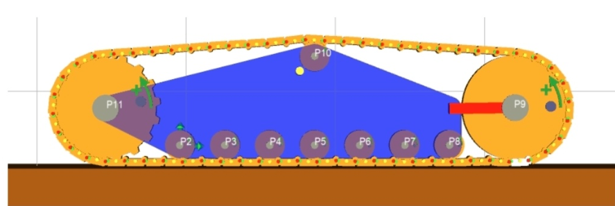
Track Configuration Diagram
The model includes the chassis's mechanical characteristics and the interaction between the tracks and the rigid ground.
The model's schematic diagram is shown below:
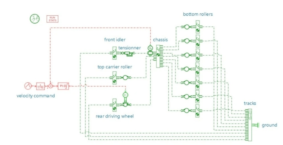
Excavator Chassis Schematic Diagram
The chassis's local coordinate system is set at the axis of the first bottom roller (point P2 in the diagram below). The relative coordinates of the rear gear (P11) are (xRearGear, yMainRollers). The remaining bottom guide rollers are arranged equidistantly with xRoller spacing. The top guide roller (P10) is located at coordinates (3*xRoller, yTop).
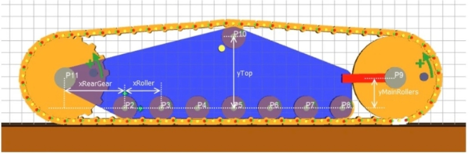
Chassis Local Coordinate System (Grid Spacing = 0.1 m)
The front wheel is mounted on a PLMTRPI01 linear annular hinge with a preset compression spring/damper. This device maintains minimum chain tension and prevents potential tooth skipping.
The front wheel tensioner is located at (6*xRoller, yMainRollers), allowing longitudinal movement of the front wheel. The default free length is 0.54 m. Tension is provided by a direct-acting spring-damper by default, but can be replaced with a hydraulic mechanism.
Track Links
The track system is modeled using the PLMBELT00V2 component, employing a chain pattern, and contains 60 links.
The links, or track plates, are modeled as two-dimensional rigid bodies, connected by elastic pivots. Their interaction with the rollers and the ground is based on elastic contact between two profiles. A contact profile can be specified for each link/roller interaction. The track link profile that contacts the rollers and the ground is a rounded rectangle on the inner side (roller side), while the profile that interacts with the rear gear is a circular pin centered on the pivot connecting the two track shoes, facilitating meshing with the gear teeth.
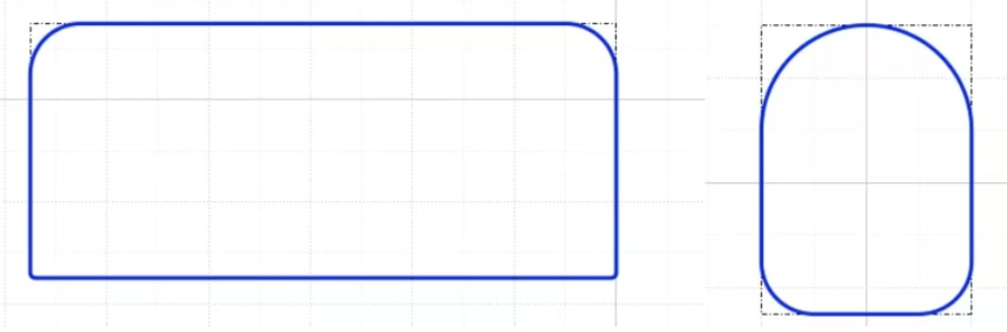
Track shoe contact profile
Rear gear
The rear gear is a 17-tooth gear with a pitch circle radius of 35 cm. Its main function is to transmit power to the tracks and drive the vehicle.
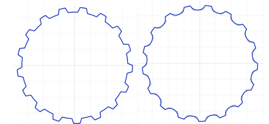
Rear gear profile (sharp edge and rounded corner versions)
The gear profile is generated using the Python script PLMGearContourGenerator.py in the $AME/libplm/PLMGearContourGenerator directory, with the following parameters:
Number of teeth: 17
Pitch circle radius: 0.35
Tooth height: 0.03
Scale 1: 0.3
Scale 2: 0.1
The profile on the right is an improved version of the original gear profile, with rounded corners added to the root of each tooth.
Engine
The power system is simplified to a torque source acting directly on the rear wheels, excluding the engine and gearbox. The control loop uses a PID controller to compare the longitudinal speed with the command value.
The PID output torque of the rear gear is limited to ±30kNm.
Ground
The interaction between the track and the ground is modeled using stationary rollers. The one-dimensional rotary port of PLMBELT00V2 is connected to a zero-speed source, and the corresponding rollers represent the shape of the ground profile on which the excavator travels.
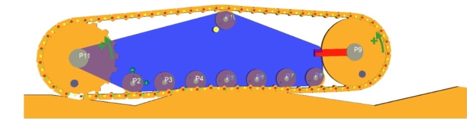
Uneven Ground Profile
The ground profile is defined by the global parameter floorProfile. The default setting is flat ground; other ground profile files are stored in the model's ${model_name}_.contour_files folder.

Defining Global Parameters for Profile Files
The ground profile can be modified using the profile editor to simulate bumps or arbitrary road profiles.
Result Analysis
The model output focuses on mechanical force analysis: chain tension, roller bearing force, track shoe ground friction, gearbox shaft resistance torque, and the impact of tensioning device oscillation on drive torque control.
The 2D Mechanical Assistant can display the track tension distribution using a specified color map.
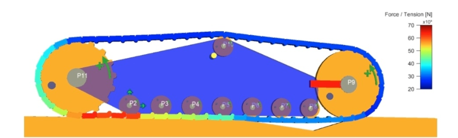
Chain Tension Distribution
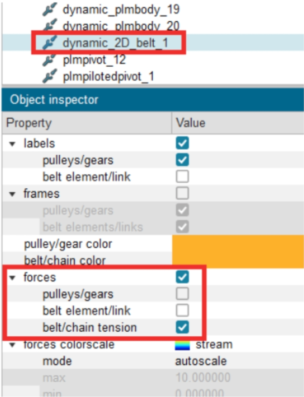
Operation Steps: In the 2D Mechanical Assistant, select the belt/chain assembly, check the "forces" option, and select to display the "belt/chain tension" item.